Regular readers may recall we recently covered a neat Arduino trick that allowed you to “blow out” an LED as if it was a candle. The idea was that the LED itself could be used as a rudimentary temperature sensor, and the Arduino code would turn the LED on and off when a change was detected in its forward voltage drop. You need to oversample the Arduino’s ADC to detect the few millivolt change reliably, but overall it’s pretty simple once you understand the principle.
 But [Andrzej Laczewski], like many of our beloved readers, feels the Arduino and other microcontrollers can be a crutch if used exclusively. So he set out to replicate this hack with that most cherished of ICs, the 555 timer. In the video after the break, he demonstrates his “old-school” LED candle for anyone who thinks the only way to control an LED is with
 digitalWrite.
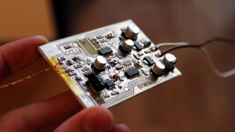
Not to say it’s easy to replicate the original Arduino project with a 555, or that it’s even practical. [Andrzej] simply wanted to show it was possible, which is something we always respect around these parts. He goes into great detail on how he developed and tested the circuit, even including oscilloscope screenshots showing how the different components work together in real-time. But the short version is that a MOSFET is used to turn the LED on and off, a comparator detects change in the LED’s voltage drop, and the 555 is used to control how long the LED stays off for.
Ever the traditionalist, [Andrzej] wrapped up this build by etching his own PCB using a variation of the classic laser toner transfer method. If this all looks a bit too much like Black Magic to you, there’s no shame in sticking with the Arduino version. At 1/20th of the parts count, and with no calibration required, who’s to say which version is “simpler”.


Kids these days with your 555s, back in my day we used to do it with beeswax and a piece of rope..
B^)
Pah! You modern kids with your beeswax and rope!
When I was young, we used to do it by banging two rocks together!
and then what?
sparks, you never banged rocks together?
Rocks? Pah, you kids had it easy. Back in my day we had to rub two sticks together!
Sticks? You call rubbing sticks together hard? Back in my day, we just waited for a thunderstorm to strike a tree so we could get some fire.
Thunderstorms? Luxury!
Back in my day, we waited to be attacked by two saber tooth tigers at the same time, and hope their teeth would grind against each other enough to make a spark while they were mauling us.
You were lucky! Try telling that to kids today, and they won’t believe you.
Oh man this thread is gold.
Now this is a positive evolution. It is good to see somebody actually put in the work of making something differently instead of simply complaining how it should have been done. The project looks nicely done.
Thinking about some old books of 555 projects that I have, we can also rephrase things like ‘the 555 can be a crutch if used exclusively’. Back when these things were popular and what the majority of people found a reasonable amount to spend, which is why there were so many projects around them. The same is valid for the arduino today.
Very nice, clean design. I wonder if it’s temperature sensive though…
Very nice, clean design. I wonder if it’s temperature sensive though…
>complaining how it should have been done.
Should have it been done with a 555? The BOM count is much higher (so much higher assembly cost/time) and I’d wager that the BOM cost is much higher too (was hoping that the author would have broken that out…).
This seems like a great academic exercise, however impractical. That’s my beef with the “but, but why arduino when…” people. Most Arduino designs can be boiled down to work on a very low cost Attiny MCU with very few additional components.
I have done this with use of 555 and other components just for fun , and because I can. I can agree that this approach is totally impractical and way more expensive than the “MCU” version. But where’s the fun when you use such a microcontroller (you know, you write a few lines of code and everything is working) ?
I am wondering if you could do it with a BISS001 motion detector IC….It should be able to trigger on the subtle changes, but it might need some extra parts for what to do when the LED comes back on.
I’ll definitely check this IC, thanks!
The point is that you’re seriously gimped with microcontrollers unless you also have a good grip of analog electronics, because you can offload a bunch of signal conditioning and logic to hardware and get away with cheaper slower micros with lower power demands and easier code.
The 555 projects are the training work to that.
Like the other day, I had the problem of level-shifting a +-0.7 Volt signal to 3.3V logic, and multiplex three such inputs into one MCU pin. I used three NPN transistors and seven resistors. Nothing else. Can you explain how it works?
This is impressive in many ways (such as the current mirror used as a constant current source to linearize the capacitor’s charge waveform), but I especially enjoy that the PCB was designed for testing. Those test pads offer easier access to circuit nodes without the “hunt and pray” method of trying to probe $@&!#%!! tiny, close-spaced, and fragile SMD terminations. Bravissimo!
I like seeing the pads for through-hole components without the holes (at least two caps done this way).
You could use a spare LM324 section to make the constant current for charging the capacitor in a linear matter.
The LM324 also doesn’t mind too much if you use it to compare voltages that are withing several volts of each other.
Nice to see you building on my blow out LED trick! As an old analog guy, I appreciate the thought here, and congrats on getting it to work. That said, I feel obliged to point out that the micro version actually works a little differently – it’s not a fixed threshold as in your analog version. If you preceded the threshold detect by something acting kind of like a high-pass filter, it would be more analogous, and greatly reduce the need for adjustment. I also think it’s possible to do an analog version with far fewer parts. I wonder if anyone will take up that challenge…
Anyhow, great to see this!
With a dual op-amp:
buffer the signal-> bandpass and amplify -> sum to offset voltage. -> schmitt-trigger (555) -> transistor. It’s two ICs and some passives, plus the regulator.
The 555 has two comparators built in, measuring against a reference that is 1 and 1/2 of the control voltage input, or 2/3 and 1/3 of its VCC, so it can be turned into a schmitt-trigger with precise limits. You force it on to begin with, to turn the LED on, and then let the LED turn itself off by setting the offset voltage sufficiently close to the lower limit and sufficiently far away from the high limit. When the voltage goes down by blowing on the LED, it triggers the schmitt off, causing the signal voltage to swing up hard, but never reaching the high treshold.
Actually, since the LED is driven by some 200 ohm resistor, it’s a fairly low-impedance voltage source. It might be even possible to drop the buffer amp and have a passive filter and then the 555 schmitt-trigger would be the only IC in the circuit.
Thanks for the suggestion, it might be actually a good idea!. I’m sure that this circuit can be done in many other better ways. Unfortunately , I don’t have free time now to check it, maybe someone else will try :) .
Uh, that’s still me, something bad happened when I’ve posted this comment, Unfortunately can’t edit it.
The comparators on a 555 probably have pretty bad offset voltage, which may swamp the mV signals you’re looking for. On the other hand, if you move up to a quad op amp, you can probably do the timing bits without adding a 555…
I’ve used the LM339D IC because of that low offset voltage. Like you said it is quite problematic in this circuit, when I tried to use a “standard” LM324 op amp for this purpose the circuit didn’t worked too well. Spare op amp,s and comparators are not wasted because I designed a multi-channel controller with use of this design block. So that one LM339D chip drives 4 channels and one LM324 chip is enough for two of them. This controller will support up to 16 LED channels per PCB. It is really nothing special , it’s just a small gift for my gf :) .
Thanks, I’m glad you like it . I’m sure that it can be done with use of fewer parts :) . I’ve actually done a version of this circuit with a buffer amplifier and a low-pass filter that doesn’t need this adjustment. Unfortunately this circuit didn’t worked too well.