Importing cheap equipment and test gear is something of a mixed blessing. It allows you to outfit your lab without emptying your bank account, but on the other hand there’s usually a reason it’s cheap. Of course, the retail price of a piece of hardware shouldn’t be the metric by which we measure its quality, but there’s got to be a few corners cut someplace when they are selling this stuff for a fraction of what the name brands are charging.
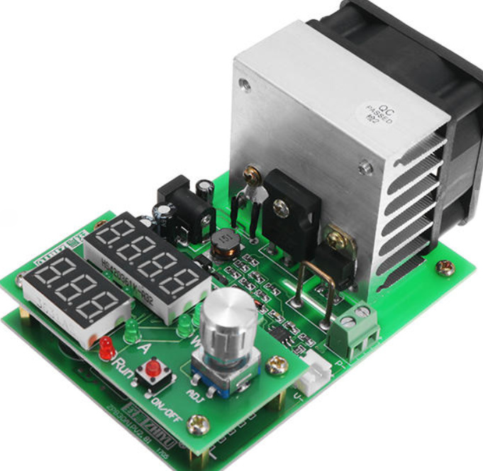 A perfect example is the ZHIYU ZPB30A1 electronic load, available from various online importers for about $30 USD. While the price is right for an adjustable load that can handle up to 110 W, it’s got some pretty glaring shortcomings. In an effort to address at least some of those issues, [Luca Zimmermann] has been working on an open source replacement firmware for the load’s STM8S microcontroller.
[Luca] quickly discovered that the device’s STM8S005K6 chip is write protected, so unfortunately you can’t just flash a new firmware to it. If you want to unlock additional features, you need to perform a brain transplant. Luckily these chips are quite cheap, and you can probably add a couple of them to your cart when you order he ZPB30A1.
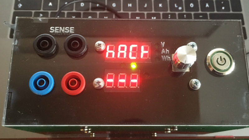
With the new GPLv3 licensed firmware installed, the device gains constant power and resistances modes (stock firmware can only do constant current), serial logging, and support for adjusting the value of the shunt resistor. There’s even a basic menu system to shuffle through the new modes. There’s still a couple features that haven’t been implemented, such as automatic shutdown, but it’s already a considerable upgrade from the stock software. Now we just need some details on the slick custom enclosure that [Luca] has put his upgraded ZPB30A1 into.
If this looks too easy, you can always go the DIY Arduino route for your load testing needs, or build a monster than can sink up to 1 kW.
[Thanks to Benik3 for the tip.]


Perhaps designing a replacement “interface module” board which is compatible with common and cheap LCD or oLED display is the next goal when software has been ironed out?
I’ve noticed that a few of the cheap power supply modules all use the same pinout connecting the STM8-powered brain-and-display board to the doing-the-work analog board. I wouldn’t be surprised if there was a family resemblance among the loads as well.
The serial logging is the coolness here. Next, automate in some control and you’ve got a super lab tool.
And speaking of STM8-driven power supplies, check out the https://hackaday.io/project/16097-eforth-for-cheap-stm8s-gadgets project, which puts an interactive Forth system on these type things. That makes it very easy to write custom voltage-over-time profiles and logging scripts and more. Maybe we need to write the support code for one of these dynamic loads…)
You got it! If any HaD folks find any PLOTTING package already existing, please share it with the rest of us. ‘Sure would help a lot of us avoid re-inventing the wheel. Mucho cred to Luca for the much needed code!
What you mean by Plotting package?
Perhaps something like qtdmm, but for loads? The ebd-m05 and it’s brethren have pc logging/ plotting software available on Zke’s website. Windows/wine only. When mine arrives I might try to write a Linux version.
So what about LogView? I used it for logging data from RC charger, that’s pretty similar principle :D
It’s Donationware and it support lot of protocols…
I’m curious as to how involved the IC replacement is.
Not very, as long as you have a hot air gun. It’s pretty easily accessible.
Well, that project took a “mind” off a load!
(grinning, ducking, and dodging)
7-segment display? What year is this?
It’s 2018, a bit over half-way through. What year do you hail from, time traveler?
Good one have to rememer. :)
Another real cool hack, modifying a standard off-the-shelf product!. +1
Your software will likely be in the next release of the hardware.
B^)
But seriously, we can all benefit from that!
It’s GPL, so no problem, as long as they release their source (with they won’t…). Anyway, you might be right…
GPL only requires that you publish changes. If you use it as is then you don’t have to release anything.
Bookmarked, might be useful one day. Thanks HaD for the info!
It’s not exactly complex hardware and they already made a schematic, so the last step is to release a new OSHW version.
Excellent point, between the new enclosure and firmware it’s nearly a new device anyway.
2 x16 LCD i2c would be nice.
+1 or an I2C OLED for graphical gauges?
And now there’s open source firmware available you can easily add any display or other features (logging?) you like.
Very useful thanks for the article and the work if you see this OP
That’s one nice dummy load and battery capacity tester for a price. Major drawbacks are minimum current of 200mA and lack of UART output. In fact it had UART output in stock version but it sends only voltage and not the current. This upgrade looks pretty cool and it solves those drawbacks. Definitely worth of trying! BTW, there is version with case, but it has uncomfortably loud fan, probably that could be fixed too.
https://github.com/ArduinoHannover/ZPB30A1_Firmware
Quote:
Adjusting shunt resistance (if replaced with e.g. 100 mΩ for an offset as low as 20 mA instead of 200 mA, not the resistance itself but the value in software)
* information_source Not needed, we can safely trim the current down to almost 0 mA by PWM
——- 8< ——- 8< ——- 8< ——- 8< ——- 8< —
I am unfamiliar with the STM8, but a scan through the programming manual sugges that (like other uC's I know) the flash can simply be erased by resetting the write protection. Quote from DM00037613.pdf
Read-out protection (ROP)
The read-out protection blocks reading and writing the Flash program memory and data EEPROM memory in ICP mode (and debug mode). Once the read-out protection is activated, any attempt to toggle its status triggers a global erase of the program and data memory. Even if no protection can be cons idered as totally unbreakable, the feature
provides a very high level of protection for a general purpose microcontroller.
So this suggests there is no reason to warm up your soldering iron (except maybe to add a convenient programming connector).
If the firmware really is not erasable, then a Load with a blank factory default chip would be more valuable to me than with a locked chip that has to be replaced.
Maybe request this from the Chinese resellers when ordering this thing. If enough people do this they might see the light and start selling unprotected gadgets.
The memory protection for a device like this is laughable from a marketing perspective anyway. These devices are so simple that Firmware can be re-created in a few days from scratch and that will not stop any "serious" reverse-engineering or "intellectual theft" as it is called by some.
I sincerely believe the only way to a better world is by sharing and cooperation and not by building walls/barriers/ to knowledge.
So Kudo to Luca Zimmerman for sharing this project.
Well, there are two mechanism of write protection in the STM8S005K6: The flash write protection vie MASS keys and the UBC write protection. It looks like both are designed to increase reliability by preventing accidental writes. The first should be handled automatically by stm8flash. The second is slightly more involved, but it should be possible to disable it by clearing the UBC option byte (one would write a suitable hex file for the option bytes by hand, then use stm8flash).
AFAIK, only the 8-pin devices can be permanently write-protected: They lack the NRST pin, so by setting the SWIM pin as an output early in the program, one can permanently prevent debugging or writes. I bricked a few of those devices that way accidentally.
Philipp
If you like this project you may also be interested in the latest revision of my Electronic Load that I am selling on Tindie. It is Arduino compatible, open source, and it supports pulsed loads. It can also be used to test solar panels, supercapacitors, and batteries. https://www.tindie.com/products/jaspersikken/jaspers-electronic-load-r3/
I’d have loved to buy one, but alas, you stopped selling them apparently.
The project mentioned here seems to be unmaintained. I found another project which seems to be unmaintained as well but which is much more advanced. https://github.com/dev26th/electronic_load