Last time we talked about a KiCAD tool it was to describe a way to make the zen-like task of manual assembly more convenient. But what about that most onerous of EE CAD tasks, part creation? Home makers probably don’t have access to expensive part library subscriptions or teams of people to create parts for them, so they are left to the tedium of creating them by hand. What if the dream tool existed that could read the darn PDF by itself and make a part? It turns out [Sébastien] made that tool and it’s called uConfig.
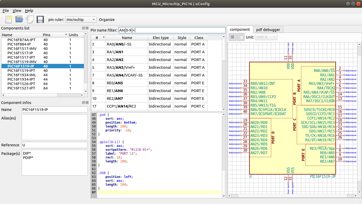
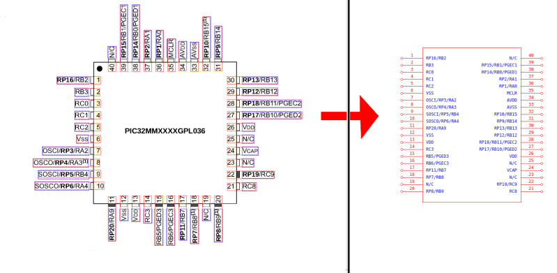
uConfig has a pretty simple premise. It scrapes manufacturer datasheets in PDF form, finds what it thinks are diagrams of parts with pin names, functions, etc, and emits the result as parts in a KiCAD library. To aid in the final conversion [Sébastien] added rules engine which consume his custom KiCAD Style Sheets which specify how to categorize pins. In the simple case the engine can string match or use regex to let you specify things like “all pins named VDD[A-C] should be power pins”. But it can also be used to move everything it thinks belongs to “GPIOB” and stick them on the bottom of the created symbol. We could imagine features like that would be of particular use breaking out gigantic parts like a 400 ball BeagleBone on a chip.
Thanks for the tip [arturo182]!


OH. I suppose you think you’re pretty clever, eh?
(Well, you are)
Yeah, inventing tools that are automagic is THE most satisfying thing in programming, that’s why it has it’s own word. It just looks like magic, sometimes even for person which made it. It’s literally distilled cleverness.
https://xkcd.com/1205/
Nice diagram. But how much time may you invest if you share your findings with the whole world and everybody saves time. How many lives of Kicad designers has this man saved :D
Am I an idiot or what ? That table is so confusing to me I spent a minute trying to understand it but cannot.
Doesn’t include spillover effects. The OP has just solved this problem for _everyone_.
OTOH: xkcd is funny.
Another task shaved off the KiCAD workflow, keep the hits comming.
the longest task associated with PCB design is eliminated as far as I’m concerned between this and footprint generation.
I’m a total n00b to kicad but I tried out this software and it worked for me. I’d appreciate it if someone could auto-generate footprints from gerbers because they are widely and freely available with cloud software.
Useful, I have mostly done simple stuff and the first time I hit the part not in library issue I usually revert to back of envelope schematics, because given the usually non-intuitive drawing tools in these packages, it’s quicker to draw everything by hand than one plus parts…
.. and BTW bitsavers.org has a few old TTL databooks etc for those old//cheap/recycled parts.
So glad I made the jump to Kicad 5 years ago. When choosing an open source tool, my advice is: first select very carefully. Normal Capitalist market rules don’t apply, open source is lean, and there is no fat in the market to support multiple identical source trees. In the end, there can be only one.
yes fucking yes fucking yes fucking yes!!!!! This is the kind of shit I’ve been dreaming of. My open source PCB empire will continue to grow but now at an accelerated rate. Component creation time is the biggest sink for PCB design.
Now this needs to be integrated into KiCAD as an “import from datasheet”.
The best recipe to have one board ordered twice is to use part libraries designed by someone else.
Very impressive job by [Sébastien] anyway.
… Or part libraries you proof checked yourself! Done that twice so far, but never had trouble with anyone elses libraries.
Awesome initiative. Silly string doesn’t work, so tools to bridge the gaps are what we desperately need!
Well there goes snapedas business model. Lol
Over the years I have found that when I have to draw parts with a large amount of pins, the IC manufacturer usually has some form of list of pins in text format on their website; sometimes, I manage to copy and paste the pin table directly from the pdf into excel.
I then use excel to format the data in the fashion that is required. adding the pin coordinates with a x=0 and Y with an increment of whatever is the standard pin pitch in the cad tool. Meanwhile I create a dummy part in whatever cad tool I use, export it to a text format (step not required in Kicad), and paste into the pin list section the data from excel, and all is left is import it back into the library, and edit the part so all the pins are where I want them.
All this saves from the pain of entering the pin information manually, in addition to preventing dangerous typos.
I have found it to work well, saves a lot of time, and it is a universal method with all cad packages that accept an ascii import.
Nice idea.
Excellent description of the workflow. That’s my method too. I also use the verbose pin descriptions to bring in to header files in embedded C so that I have a full list of all the pin functions available in my code.
Wow, just wow!
This my friends is the best feature since fried potatoes…
Absolutely awesome. !!!
Please add my voice to the VERY grateful. Thank you 1000x
Cool. But unfortunately it doesn’t always work. I decided to test it on TUSB2046 (datasheet https://static.chipdip.ru/lib/126/DOC001126607.pdf ) and it didn’t manage to find a package.
Please let an issue at https://github.com/Robotips/uConfig/issues and I will fix it ;)
Thanks
This looks very interesting but sadly the windows download link errors out :-(
Does anyone know where the windows binaries exist ???
Dave