A high-resolution LCD or OLED screen is a commodity component that we can buy on a little breakout board and plug into our microcontrollers without spending more than a dollar or two. We can buy them in sizes ranging from sub-postage-stamp to desktop TV if our budgets stretch that far, and they are easy to drive in every sense of the word. It is not so long ago though that a high-resolution LCD, even a small one, was a seriously expensive component. In consumer electronic devices such as camcorders engineers went to great lengths to avoid those costs, and [12voltvids] recently took a look at one of them.
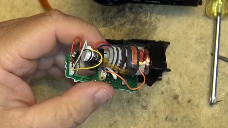
Inside the viewfinder of a miniaturized Sony camcorder is a CRT. It’s fairly mundane in the scheme of CRTs, in that it’s a monochrome device with no unexpected features. Except that is, for one thing. It’s tiny, with only a 0.5″ inch screen size. Everything else is the same as your vintage full-sized TV, it has an electron gun and a deflection and focusing coil pack, but the entire device has been miniaturized to the point at which the coil pack is larger than the screen it is driving. On the accompanying PCB are all the support circuits, including a tiny flyback transformer and a single IC – a Rohm BA7149 electronic viewfinder driver that is as near as possible an entire CRT TV on a chip. That’s it, the whole device runs from a single 5 volt supply.
He doesn’t give the date of the camcorder, but given that it looks as though it uses 8mm cassette tapes and has a curved miniaturized design rather than the angular black exteriors that were fashionable earlier we’d guess it to be from some time around the year 2000. To give it some context, at the time one of the hottest pieces of consumer electronics would have been a Diamond Rio MP3 player, and if your desktop PC had the first of the AMD Athlon processors you probably considered it to be about the fastest you could hope to own. The surprise then is that Sony still considered it more economical even at that point to use the CRT and associated circuitry than a tiny LCD. Either way we’d agree with him that it’s a keeper, a fascinating curio for any electronics enthusiast. If we see an old camcorder going for not a lot, we’ll certainly give it a second look after this.
Thanks [Rahul Chawre] for the tip.


Try a colour tiny CRT from camcorders. That is super-cool. CRTs amd vacuum tubes are the ultimate wizardery ever.
That sounds amazing. Never saw one of these…
I have a couple of mono crt viewfinders, I made a night vision scope with IR led’s analogue camers, it worked well but batteries only lasted minutes.
It was from a 1996 model year CCD TRV11 camcorder. LCD screens were also common back then, but the reason for the B/W CRT viewfinder was for manual focusing.
Color screens were just not good enough. Even with my current camera, which features an ultra sharp OLED viewfinder they have to include a focus magnifier to aid in focusing. Something that was not needed with a monochrome CRT because the CRT was more than sharp enough for focusing the camera manually under all conditions.
Hitachi (also sold by RCA) made a small beam index color CRT that was 1.25″ but it was useless to focus with due to it’s low resolution. The cost to make this little CRT in the day was probably higher than a small LCD.
I currently have 2 digital 8 cameras. One from 1999 and the other from 2000.
The 1999 model uses the same view finder as in this video, and the next year it had a color LCD.
The LCD is useless from a focus point of view. Just doesn’t have enough detail so focus the camera.
For anyone wondering: this seems to be the Sony CCD-TRV11. It also had an LCD on the side that you could fold out. Given that the manual has a 1996 copyright, that is likely when it was released. Even in newer Hi8 devices Sony released closer to 2000, they were still using the CRT viewfinder. For example, the CCD-TR3200 my parents bought in I think ’99, also had one.
Now we just need 4 of them for a nice clock! :)
Or two displaying a group of two digits each, save some space and money :) Put a pair of LEDs between them for the colon
Those things cost next to nothing. At least here in Germany old VHS/Video8-Handycams are incredible easy to find for free.
>”Sony still considered it more economical even at that point to use the CRT and associated circuitry than a tiny LCD.”
The CRT had no input lag relative to what went into the tape, and it had superior resolution to the LCD, so you could actually see when you’re in/out of focus with the camera. The LCD on the other hand was pixelated which gave the false impression of sharpness, yet when something moved it became ghosted and blurry. LCDs had to become better and cheaper, and the DSPs a whole lot faster (and cheaper) to get you equivalent performance of a tiny black & white CRT.
this. I always thought the first LCDs were a step back from the crisp sharp CRTs they replaced, the CRTs were just better than LCDs for quite some time in this application
And for another point, the dynamic range of an LCD was poor compared to the CRT, so the view became washed out and you couldn’t judge the lighting correctly. What you saw on the LCD was not what you got on the TV screen. That’s still the case, but then again the eyepiece viewfinders have dissapeared from cameras almost entirely, so it’s a moot point because nobody’s got anything better.
My sister bought one of the first VHS-C camcorders with an LCD viewfinder. It was absolutely terrible – low resolution being the worst of many complaints. But she *needed* the colour for her use-case.
Until LCDs came along, I never saw a consumer grade camcorder with a colour viewfinder. I don’t know if even mid-range professional/studio cameras had colour viewfinders.
Also relevant: some newer units had LCD with colour backlights. This only really became practical when blue LEDs did, sometime in late 1998.
Have a DVD camcorder here which uses this method and kept it around because it does have some use even though long since obsolete thanks to phones with fractions of a GP count.
Still need to figure out how to convert the drive so it can read full sized DVDs :)
I’ve been looking for a cheap source of tiny TFT displays. Something like 320×240 px with less than 1 inch display size. One can get them as spare parts for viewfinders, but they’re quite expensive.
Motorola V3 Razr phones, secondary display… some other feature phones from mid noughties too.
Ha! Noughties. Haven’t heard that one before. I love it.
I have several of these, both colour and mono that I use when needed. It is easy as they just take the composite 0.3 sync, 0.7 signal of any TV input.
One of these would go good into a tabletop slide viewer with an arduino pong or invaders game.
You took the time to count the words to point that out.. Just saying :)
You know, you could just copy that to software which count words, like word or notepad++…
But Word’s result could be wrong…
(sorry, couldn’t resist)
I wonder what the other two pins on the connector are for?
One I investigated used the viewfinder circuitry to generate H & V sync pulses for the rest of the camera.
Composite video (presumable from the sensor & processing) to the viewfinder, sync back down to the recoder (tape in those days).
Why have a separate sync separator when there’s one already there! Problem is, camera wouldn’t work without a functioning viewfinder!
I have one or two around here somewhere. Now to make one into an oscilloscope, to feed stereo audio into the two deflection coils. In small TV’s that I do this to, the flyback has to have an inductive load on it when disconnecting it from the horizontal deflection coil, or no HV. To make the time based display use the vertical as horizontal (rotate the coils 90deg.) Feed audio from a small power amp into the other coil.
Reminds me of the Sinclair mini pocket TV
http://rk.nvg.ntnu.no/sinclair/televisions/tv80.htm
https://www.thevalvepage.com/tv/sinclair/ftv1/ftv1.htm
http://www.r-type.org/articles/art-054.htm
$ony also had a “Watchman” that utilized a “bent” CRT.
Back in the days of CRT dominance, moms would constantly tell their younglings not to sit too close to the TV because it wasn’t good for them. Now imagine strapping a CRT one inch from your eyeball. Getting too many X-Rays seemed possible, but I bet they thought of that and did sufficient remediation.
Hiya, Im here from the 80s to inform you 1) the X-ray thing is modern paranoia and highly blown out of proportion. Stop typing, I saw that video too. It is. Deal with it. 2) The reason parents told kids not to sit too close was because their kids giant melon of a noggin was in the way of the 20″ 4:3 display area of the CRT television set, they just used the eye thing as a viable excuse. 3) No remediation needed, besides, it ran off of like 5v…..its tiny…..sure the support circuitry bumped it up some for the electron boil off and guiding fields, but they’re nothing like the thing the dentist points at your head before fleeing the room. The 80s were cool, the 90s were fun, the noughts were awesome and then sucked. You are now caught up on the before times, please refrain from besmirching them with made up ‘hur dur past people were stupid’ modern hipster snobbery. Or we will have to issue a T-800 to address the next infraction. This has been a message from the Temporal Coherence Division of Raytheon Industrial Controls, LLC powered by Retroencabulator technology under the supervision of Rockwell Automation Systems. The TCD would like to remind you that an interval overdose may cause a serious temporal imbalance. No trees were harmed in the sending of this message, however a large number of electrons were terribly inconvenienced. As such this message is known to the state of California to cause cancer under Prop 65 regulations and must display this warning at all times in areas accessible by the public.
I ran one of these weekly for the better part of my time in high school. Sometimes multiple times a week filming entire basketball games for the team to review afterward and then during the day for the school “news” segment. Ahh, the dangers of being a nerd. The X-Ray exposure must not be too bad. I’m 33 and still have better than 20/20 vision.
Would such a small CRT generate X-rays? AIUI, X-Rays were possible in 19″ or larger, but mitigated through design.
I’ve just got to ask. Does CRT tube size matter with x-ray production? Is the point that small tubes produce less light and so less electrons need to be fired at phosphor to make less glow and so less x-rays? The effect, I suppose, is offset by the fact that it is an inch or so from the eyeball rather than, hopefully, many feet away for a TV. :-) I assume that a CRT that has 100x as many square inches of glowing phosphor would produce 100x as many x-rays but there would be the same yield rate per display surface area. Larger tubes don’t get extra “nasty” as they get bigger, beyond what scaling does. Is that right?
Or the X-ray exposure thing is massively overstated by modern hipster scaremongers who also believe just hearing the word lead or cigarette immediately endangers their milksop waste of a life and already given them cancer, and that the only smells in the world are nice ones. They’re too busy trying to make it back to being bald and in diapers instead of making the most out of and enjoying the one play through we get on this rock. And, sorry not sorry, I refuse to take technical advice from a generation that would be confused at how to operate a pulse dial phone…..or pulse dial from a DTMF phone…..
Thinking of this reminds me of the communicators used in the show “Space 1999” — they built a mock-up prop with a real CRT from a Panasonic TR-001 for the show back in the 1970s, but apparently only the CRT fit in the profile of the device (never mind that they would also have needed a receiver), so a cable dangled out the bottom of the prop.
http://catacombs.space1999.net/main/models/w2pcomlock.html
I have both a BW and a color cam corder monitors. Bought the color monitor from a surplus house in 80s to replace BW monitor on my VHS-C camcorder. It worked but sucked power like crazy reducing recording time. Also have just as rare 3 image tube Sony color camera that I dumpster dived for. Someday my family will put it all up on Craigslist for $50….
Does anyone have a model number for the 89s camcorders that had the color CRTs?
Hi, congratulations on your project. Could you help me, I don’t have much idea of electronics. I see that you use 3 wires, 2 black and one yellow. Could you tell me what each one corresponds to and the voltage? What are the positive, the negative and the video? From already thank you very much.
Is the screen glass?
Imagine a VR helmet using 2 of those. Neuromancer style.
great job writing about “the one smallest ever made” and NEVER ONCE MENTIONING WHICH ONE IT IS!
I have one of these, from a Slimcam. The thing is ridiculously small, but I can’t find a datasheet on it. I took the plastic bezel and the yoke off… the electron gun neck is only slightly larger than 1/8 inch..