Conventional 3D printing and other additive manufacturing methods are highly effective at producing parts of irregular geometries that are difficult or impossible to create with other methods. However, there is a whole set of compromises that come with it – material uniformity, strength, and size are just some that come to mind. There are, however, other techniques that can be used in conjunction with these technologies, and the use of so-called “extruded elements” may be one of them.
The idea is to break up large models into a series of smaller mutually interlocking pieces of an extruded form. This is done by importing an STL model into OpenSCAD and processing it with a special script. This script essentially intersects a matrix of extruded forms upon the original part geometry, allowing it to be printed as a series of seperate pieces that can later be assembled. The instructions are long and detailed, but are an accurate guide of how to create your own extruded element parts.
There are options to customise the process, allowing for filled and skeleton type extrusions and various ways of interlocking the parts. There are interesting implications for this technology, thanks to the benefits of interlocking parts. Particularly, it could have great benefits for the repair of damaged structures and for building objects that exceed the size of the build platform on a smaller 3D printer. The technique looks especially good for building up lightweight cores for big objects. [Toby] is working on a stand-up paddle board.
We look forward to seeing how this particular project develops. We’ve seen other techniques to build large printed structures, before, too – like this giant RC F1 car.


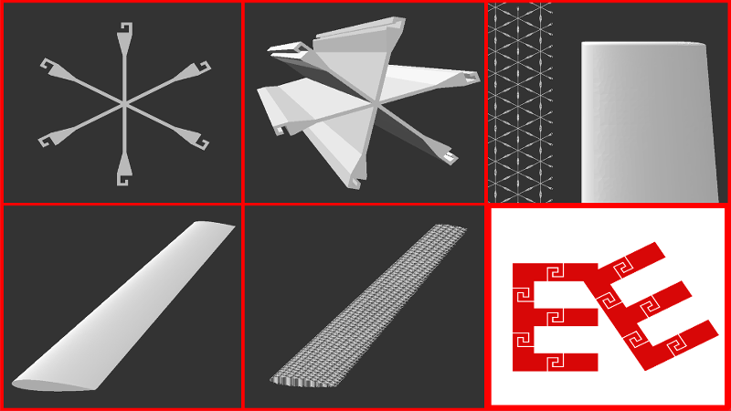
Taking the “E” example as shown in the image, the strength of each ‘leg’ is actually only a third of what it would be if it were a solid piece.
Great for assembling things from smaller bits (eg: shipping constraints on size), but terrible for things that require high strength to volume/weight ratios (like aircraft parts).
Maybe you could fill the connections with epoxy, that should make them the strongest part of the body.
Hi! I’m Toby from Extruded Element. You can alter the ratio of Element Ligament to Hook Size (Defined by the Hook Tip Width) within the Free-for-Makers Library (check out r/ExtrudedElement for tips and project progress).
This interlocking design, and using it for a paddle board reminds me of someone who uses interlocking laser cut sections in a triangle pattern: http://www.sheldrake.net/quarter_isogrid/
That is so baller, fm’!!! I’ve been looking for someone who has performed similar feats for the vinyl wrapping difficulties I will encounter in January when I’m done printing the SUP board. I love his page styling.
For even larger structures – https://www.youtube.com/watch?v=aoSzOL9k990
That team has even incorporated FEA into their building-block GUI. I have a long way to go with Extruded Elements.
Apparently he’s going “Patent Pending” on a way of building items that has been used for generations in the building of toys and other items. Classic case of, “Hey I can do dovetail joints with a 3D printer, I’ll patent it!”, because **that’s original**.
Kudos for putting the software rather than doing it manually like the rest of us, but “Patent Pending”? Really?
If he created a new algorithm in the software to do it automatically then that alone is patent worthy. He does run the risk of having his patent invalidated due to prior art if any other company already has such an algorithm patented. In other words, don’t knock his patent pending unless you have read his patent and understand what he is claiming to be unique, The interlocking patterns may not be unique but his algorithm for automatically placing and modifying the 3d file may very well be.
Read the patent! For me it looks like only the structures are patented and NOT the algorithm. The script looks great (haven’t tried it yet) but everything generated with it is patented (pending).
Thanks for the input Lee, Mike & skikovienna. My intent is to enable the Makerspace freely for non-comm./personal use and commercialize on the Extrusion Industry and Commercial AM applications.
Coupled with a 5 or 6 axis mill / laser cutter such is offered by TRUMPF or BLM-GROUP would enable an in-line extrusion and profiling process. You could have aluminum extrusions that span a golf course when assembled, rolling hills and all (I’m neither good nor enjoy golf, I love existing on the green landscape though).
Bookmarked this one. :)
Check out the subreddit r/ExtrudedElement if you would like to see SUP Board and My father’s memorial progress using the Extruded Element Technique.