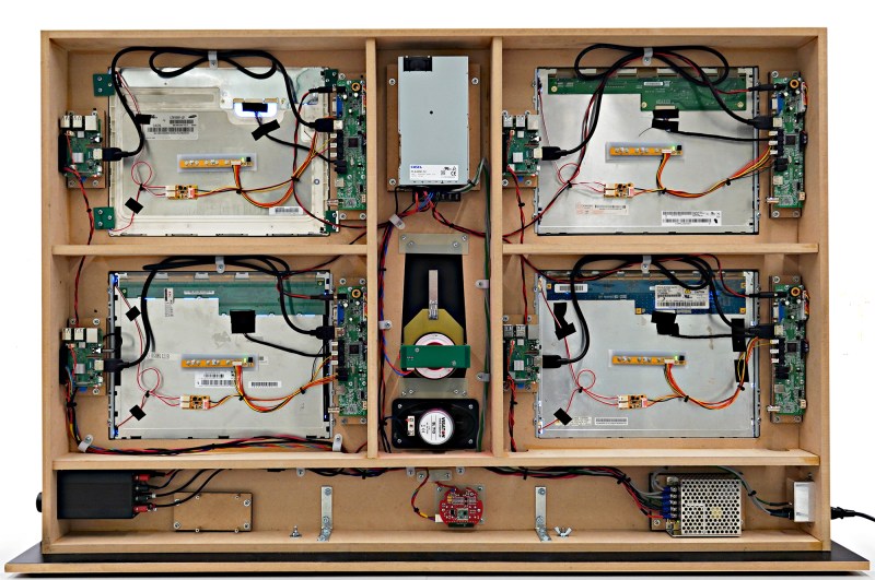
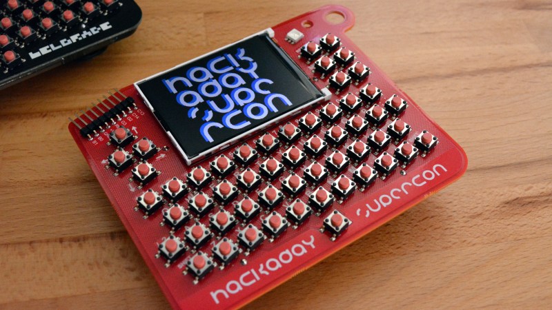
Let’s play a guessing game. Shown here is a sneak peek at the rear view of a hardware demo being built specifically for the Hackaday Superconference in Pasadena this November 2-4. It’s sure to be a crowd pleaser when finished, but if you’re anything like us, studying what’s behind the finished face of a project like this is even more satisfying than seeing the final product.
If you think you know what it is, you can score yourself a free hardware badge from the conference! Leave a comment below with your best guess about what this is — we’ll pick whoever is closest to win the badge.
Want a closer look? Click here to embiggen.
Update: We have a winner!
It didn’t take long at all for Zardam to realize this a replicate of the console for the Hal 9000 computer from 2001: A Space Odyssey. Congrats!
Some comments on the build from Voja Antonic:
The red round board at the bottom is the PIR motion sensor, the part of another project which is not related neither to HAL nor to the badge. There is a clearly visible 915 MHz module, which is disconnected and has no function in this project.
It is connected to the lower left Raspberry just because it has to be supplied with about 3V and it uses Raspberry’s LDO. It also generates Reset signal for all four Raspis, as it turned out that the 5V supply (bottom right) delivers the slow-rise voltage when turned on, so Raspis won’t boot at all without the external Reset.
When someone walks in front of HAL, motion sensor randomly triggers one of 30 HAL’s sentences from the movie. That’s why the lower left Raspberry is connected to the amplifier and has an extra wire from the motion sensor board to GPIO 24.
And the demo video:
The Prize for Guessing Correctly:
Voja Antonics builds beautiful hardware. The Hackaday Superconference badge is a piece of art, as is the Hal 9000 console. Voja will be at Supercon along with hundreds of other awesome hackers. Come join us for a weekend you’ll never forget!


It’s a scoreboard.
What is that red board bottom centre?
i’m not talking about the bottom pic.
What is that red board bottom centre of the 1st pic ?
i have a feeling this will be related to the badge
Digital info panel with 4 screens, each powered with a RaspberryPi, possibly interacting with badge
Something with a screen (OLED/tft), RFM69, 4 wires leading to some other tiny thing pointing to the from of the panel.
Four lcd screens, connected to Raspberry Pis with adapter boards for connecting said screens to HDMI.
Seems to have a speaker, so maybe a display for connecting and using the badges to play a game ?
Ooh, good call with the badge connection!
Several Pis connected to screens with some speakers and mystery hardware in the bottom. I’m going to guess that it’s a comparison between different ways to do a certain task.
And almost certainly badge related given that red board on the bottom.
Looks like a multiplayer Pi gaming console to me :3 (I already have a ticket, but you grabbed my curiosity!)
An arcade game for 4 players
HAL 9000 Console ?
What a guess! This is indeed the correct answer. Voja Antonic who designed the hardware for the Supercon badge has been working on this replicate of the Hal 9000 Console to show as a demo at the conference.
We’ll be in touch shortly to get the badge you won sent out to you. Congrats!
I’m sorry Mike. I’m afraid I cannot do that.
LOL!
Yep, that was my first thought too.
Congratulations, zardam!
Here’s a short video:
https://youtu.be/44kpwE2Mv1I
well miss directed.
:)
Nice touch with the ambient noise played the whole time! Sounds just like the systems of Discovery One.
Does it, umm, have any precautions it can take against people trying to unplug it? ;)
It’s the noise of the fan on the 12V/20A power supply, erroneously ordered instead of the fanless one. When you add the sound level compressor of the camera, it really sounds bad. Will be replaced soon.
Four LCDs with touchscreen controllers, power supply in lower right, audio amp/volume control in lower left, speaker in middle above the bottom partition, another power supply top center. I don’t know what the bottom circular board is or the vertical trapezoid-ish thing is in the center. I’m guessing some kind of 4-player touchscreen game.
That is, four LCDs with touchscreen controllers driven by R-Pi’s, of course.
Hack a day gaming console with multi view points
It has 4Raspberry pis connected
Looks like a display panel using 4 Raspberry Pi’s to drive 4 touch screen monitors (~10”?) independently with a common sound source in the middle.
A 4 screen game or customer interaction piece. Possibly a data monitoring station? Whatever it is, looks great!
So, four tfts with a pi each. Bottom left pi looks like the master. It has audio out and the io connector goes to the round red board, which has a 433/960 MHz transceiver but I’m guessing also a display on the front which is what it’s being used for.
The coil(?) centre middle is maybe inductive charging or a magnet.
I’m guessing maybe you dock a phone on it which the pi’s talk to?
IO breakout only from lower left Raspi to the “unknown” round red PCB. Discuss. :)
“Mirror, mirror, on the wall: what talks are happening, and in which hall?” “I’m sorry Dave, I can’t do that.”
ah damn… I knew it, too.
Tooooooo late :3
I have to agree with pretty much everything said here and could go on about 4pi yada yada however what this is built for is supposed to be for a hack conference. So I am going with what it’s for vs what it’s obviously made of.
I believe it was made to have some kind of interaction hack for one individual at a time since it’s too small for a multi interactional device. This hack will lead the individual from one screen to the next and then incorporate all four at once revealing a rabbit hole. At which point Alice, it will be up to you to push the big red button and choose if you fall down it or not. Thereby hacking your way into Woderland and the altered reality thereof.
I highly suggest wearing your top hat, bringing your drink me eat backups and a tea cup, (no one likes to drink out of a dirty cup).
See you in the other side!!
I see that I have to explain the red round board at the bottom. It’s the PIR motion sensor, the part of another project which is not related neither to HAL nor to the badge. There is a clearly visible 915 MHz module, which is disconnected and has no function in this project.
It is connected to the lower left Raspberry just because it has to be supplied with about 3V and it uses Raspberry’s LDO. It also generates Reset signal for all four Raspis, as it turned out that the 5V supply (bottom right) delivers the slow-rise voltage when turned on, so Raspis won’t boot at all without the external Reset.
About the audio amplifier… when someone walks in front of HAL, motion sensor randomly triggers one of 30 HAL’s sentences from the movie. That’s why the lower left Raspberry is connected to the amplifier and has an extra wire from the motion sensor board to GPIO 24.
Did you build the HAL 9000 module in the center or source it from Thinkgeek (or some similar replica store)?
Built it from scratch
Sounds like a future write up to me????
That hope RF module really threw me off.
Hal9000 with four monitors
Hal is baaack would be nice if they could make the third final book in movie, i miss hal voice loll
Third (2061) or fourth (3001) book? Actually, I’d settle for a remake of 2010 — that movie was gosh awful (despite Roy Schieder)… or if Morgan Freeman can get off his rear, a decent production of “Rendezvous with Rama.”
oh never heard of the 2061 ???
“this a replicate”
Does it sing “Daisy”?
It should do that as part of the shutdown sequence.
Good point :)
Of course, what is HAL without Daisy? :)