The inside of classic radios holds wonders that the sterile chips and SMD components of today’s circuits can’t hold a candle to. Chunky resistors and capacitors, vacuum tubes with cathodes aglow, and seemingly free-form loops of wire forming inductors will all likely make an appearance. But the most fascinating bit of any old radio was connected to the tuning knob: the big variable capacitor with its interdigitating metal plates. Watching one at work, with its plates evenly and finely spaced, is still a joy to behold.
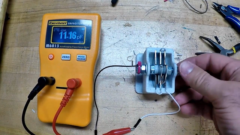
In an attempt to recapture a little of that magic, [Jeremy S. Cook] came up with this home-brew variable tuning capacitor. The frame is built mainly from 3D-printed parts, which supports a shaft made from a common bolt. Plates are fashioned from stainless steel fender washers cut in half; the fixed plates are press-fit into the frame while the rotary plates ride on the shaft. The spacing between the rotary plates is maintained by printed spacers, which also serve to lock the rotor into one solid unit. [Jeremy]’s prototype, for which he provides STL files, can be tuned between about 7 and 15 pF. Check out the build in the video below.
We love the look of this, and we can imagine custom tuning caps would come in handy for certain retro radio builds. The tuning range is a little narrow, but that could be fixed with more plates or closer spacing. That might be a tall order with thick steel washers, but we’ve seen really thin aluminum machined and closely spaced before, so this might be one approach to higher capacitance.
Thanks to [Baldpower] for the tip.


Nice example of building an electronic component from first principles, thanks for showing.
My sense of aesthetics then takes over and ponders why after a lot of work went into the 3D CAD model of the body, the shaft is then turned by the unadorned bolt head and not a printed knob :)
Fair enough. Probably would have been a nice touch!
Unfair criticism. If you buy a variable capacitor, it’s not going to come with a knob; it’s going to come with a bare shaft at best. Great hack.
Good for concept but it’s a mere trimmer compared to a MW tuner cap for a crystal radio. Maybe on VHF as a tuner with grounded enclosure. 365 pF, that was the big old standard. The wiper is the real trick to pull off.
The wiper is indeed the trick, but it’s not essential. I’ve seen antique radios that used a loop of copper braid to electrically connect the rotor to the frame.
Nice build, just one big mistake when working with RF – the plates should be made from non-ferrous metal so a washer won’t really cut it.
This, and there’s no temperature compensation.
Can you elaborate on this?
I’m in the process of building high-power capacitors for a project, and using steel plates 6″ in diameter a couple of inches apart. I’ve been doing a lot of research, but have found no mention of ferrous plate problems. (The obvious ones of ESR from lead resistance and plate resistance, but nothing specifically about ferrous/non-ferrous.)
In this case “high power” is 600 watts at 13MHz. Will using steel plates be a problem for me?
The skin depth is smaller for magnetic materials, and a smaller skin depth means RF currents are forced through less metal and therefore encounter more resistance. At 13 MHz, the skin depth in copper or silver is a bit under 20 microns, vs. maybe 1 or 2 microns for steel (depends on the magnetic permeability, which can vary quite a bit). On top of that, the conductivity of steel is much lower than that of copper — 10 to 40 times worse, depending on the steel in question. Plating one or two skin depths’ worth of copper or silver over the steel will mean that the RF current barely ever notices the poorer metal, with the side benefit of protecting the steel from rust (at least until the plating gets scratched).
Whether the increased effective resistance is a problem depends on a lot of factors — how much does the Q factor of your resonator matter, how big is the capacitor and therefore how much heat can it dissipate, and so on. I would expect that 6″ plates would be able to shed a lot of heat if they have free or forced air flow, so you may be fine just accepting the high resistance and moving on.
Thanks for that! It makes perfect sense.
I’ll start by ignoring the ESR issue, and I can easily silver plate the plates if needed. Right now the focus is on getting the project to work, efficiency is not the immediate concern.
Yup it’s all about that skin effect. The weirdness of the world increases with frequency. One of those weird things is magnetic domains in iron particles forming their own random RF circuits inside a simple piece of wire.
Anyway, a good capacitor should have consistent impedance across a range of frequencies, if the impedance changes or worse starts adding parasitic inductance into the picture then it’s a very bad capacitor. Also your capacitor must have as little series resistance as possible, with iron having 100 times higher resistance than copper or aluminium you’re already on the back foot there.
tl;dr, ferrous metals resistance increases with frequency, and its resistance was already terrible.
A snifter of Silver plate would probably do as at RF frequencies most of the current travels over the skin of the material.
If you look at the good RF cable / Capacitors or what ever they all get silverplated for this reason!
You can also start with brass washers instead of steel. Most of the commercial variable capacitors I’ve seen didn’t bother with silver plating, and many use aluminum, which isn’t nearly as conductive as brass.
True: Brass (15 MS/m) is much better than iron (10 MS/m or less for alloys), but it has less than half the conductivity of aluminium (37 MS/m). There is a reason, that most commercial products use Al.
Thanks for the writeup Dan!
Thanks for the build! Makes me want to break out the printer and print some crystal radio parts.
Nothing about that last sentence seems right, does it?
Wow! You have a crystal printer??!!
I’m guessing same as the one in Ocean’s Eight.
The shitty “tree of knowledge” electronics kit I had as a kid had something like this. As well as a breadboard you had to push the copper clips into yourself. Layers of mylar sheet and thin badly-punched copper you pushed out from a sheet, interdigitating in a corresponding manner. Worked for the AM radio stuff it was designed for, especially considering what a piece of shit it was. No reason this one couldn’t. He could just use bigger washers, more of them, and closer spacing, if he wants a larger value.
In mine, the mylar was about 0.1mm thick (guessing) and the copper maybe .3mm. IIRC it was nominally 65pF but that’s really pushing my memory.
As it is, I would fear this one is susceptible to being de-tuned by nearby objects, like people, since it’s such a low value and not a particularly dense bit of capacitating.
Really this cap is more of a giant trimmer than tuning capacitor @ 7-15pf. Good effort though…keep it up!
Thanks! Yeah more of a proof of concept or an educational tool than anything else I suppose.
I have an Acrylic design which is similar just laser cut rather than 3D printed …looks cool though!
I’ve been making laser cut acryic variable caps also, using adhesive copper tape for the plates. KInda tricky to make everything work well, but works like a store bought cap when done… and you get exactly what you want… BTW Kapton tape ( 1 mil ) can be used as a dielectric, which allows direct physical contact between rotors and stators, without any “shorts”… and also allows really high capacitance values..Kapton diecectric constant is 4x greater than air.
But it’s better than that. Today’s radio devices don’t use variable capacitors at all, since everything is digitally tuned, which has driven the price of variable capacitors way, way up, since they’re now a niche product. It’s good to have the skills to make one from scratch when you need it.
They don’t use variable capacitors, they use varicaps :-) In most PLL synthesizers you have a varicap diode or two in the VCO. Only if you go fully digital with a DDS (direct digital synthesizer) you can produce a variable frequency without a variable capacitor. But you need REALLY fast digital logic, if you want a DDS in the GHz range.
I really like the idea! But I would have gone with solid copper plate, or in a pinch, copper-clad PCB (if you are a serious hacker, you can even figure-out how to remove the copper-cladding from a PCB without damaging it, or losing fingers).
yeah copper sheet is commonly available also you can get the 0.2mm PCB material they use to make multi-layerboardswhich would ramp up the capacitance no end and keep the breakdown voltage high if you were making one for transmit… And I suppose you could also silver or tin plate it to stop it oxidising etc
Thanks! Using a PCB is an interesting idea, since you could get them cut however you want.
Thin PCB material is a great idea, but I think the thing to do is to separate them with thin “washers” of polyethylene (i.e., plastic shopping bags) or mylar. These are much thinner than 0.2 mm and will get you a lot more capacitance per pair of plates.
You could just use single sided PCB material for stator and rotor plates. Then the plates could touch each other (copper side to the epoxi side of the next and you get a tight packing.
I would have gone with plastic washers instead of 3d-printed spaces. You can get them in the hardware drawers of your local hardware or construction store, and for cheap at that. Should also have brass washers, which should be both solderable & better conductors that the steel (or whatever else) washers that actually got used. And probably aluminum flashing for the case (work over real good with sandpaper, then form a pool of solder where you want to connect things, scrape the oxide layer away with a knife or something whole the solder is still liquid, and presto! Solderable aluminum!).
Thought the same about using thin nylon washers for spacers. The home stores also generally carry very thin rubber or neoprene washers too. I have never seen brass fender washers of any decent size though.
I was curious why no one had suggested cutting aluminum sheet instead of washers. Don’t know if they’d work here, but using snips or other hand tools to rough out several fins; bind them together with a bolt or vise; then sand/file them all down to a uniform shape…seems reasonably viable to me. I also assume tinkerers back in the day probably did something similar, even if it were steel sheet.
“cup” drill?
It’d both make the center hole and cut out perfect circles.
Greenlee chassis punches, or a “fly cutter” ( AKA “widow maker” drill )