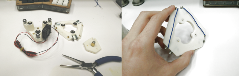
3D Printer tool changers are bedazzling to watch, but even failed attempts at tool changers can yield something marvelous. Such is the case for [Raymond] who transformed a tool changer attempt into a perfectly capable z-level probe that uses the hotend itself as a limit switch.
The secret sauce behind this mechanism: a kinematic coupling. This coupling takes two planar surfaces and perfectly constrains them relative to each other by mating them together at exactly 6 points of contact. The result is that repeatedly separating and joining the two surfaces will always land them in the same spot within a few microns. To transform these surfaces into a switch, we need only run a small current between the points of contact. That was easy since there were all-metal balls and pins making the connection. Both surfaces are held together with magnets with the upper surface holding the hotend. To trip the limit switch, the printer simply lowers the z-height until the hotend “probes” the bed, defeating the magnets and breaking the current. Presto! No switches or P.I.N.D.A. probes. Just good old fashioned electricity and steel pins.
With so much focus on pricey probes and repeatable switches, it’s great to see some good old-fashioned geometry guiding the precision behind this printer’s sensing. It’s also heartwarming hear that the whole project was actually inspired by another coupling-equipped 3D printer that landed here a few years ago! Finally, if you’re curious to see some other folks getting some more mileage out of kinematic couplings, have a look at this homebrew CNC touch probe.


Looks like it was from 22 March 2016, I couldn’t find any stl’s or thingiverse links
this is similar though https://www.duet3d.com/DuetAddons/DeltaSmartEffector
I like the idea of a DC motor. Back EMF sets the current, Measure the current across a current sensing resistor, feed into your micro and that is your touch sensor. Use a low enough drive voltage to limit the max speed. Ideally use a motor with a low rotational inertia. With no additional mechanical construction required, the motor does it all for you. Z touch: check, X touch : check, Y touch : check. The one issue might be the rotor’s z motion if the motor is super cheap. Otherwise a simple touch solution.
The duetWIFI uses trinamic stepper drivers, other than being very silent due to smooth waveforms
they also have the ability to measure torque, so in theory they might be able to be used in this way.
I recently stumbled across this, which I’m thinking of trying to adapt for my delta
https://www.precisionpiezo.co.uk/product-page/precision-piezo-orion-kit
How does the kinematic coupling have anything to do with the probe? I even clicked through to the link, reviewed the photos in zoomed-in detail… I still seem to be missing the point here. Is the current travelling through the hot-end and into the (conductive?) stage? And when the hot-end crashes it makes a slightly better (less resistive) connection on the spheres/balls? I guess I’m just still in shock and awe from the last hackaday article I read, on the apple mini mac, hopefully I’m just temporarily stupified.
This is my blog post. I wrote it a long time ago and have since given up on the concept. The spheres complete the circuit through the steel standoffs that complete the kinematic mount, so if any of them lose contact, then the z-probe is triggered.
Downside here is that you need to overcome the pull of the 3 magnets before the z-probe triggers, and so you have this catch-22 where the pull needs to be sufficiently high so that the hotend remains attached during printing, but still low enough so that you can still reliably trigger the probe on initial contact.