All the cool kids are doing it these days, or more like for many years now: you can get a laser cutter for a song if you don’t mind doing your own repairs and upgrades — you know, being a hacker. The downside is that some failures can really ruin your day. This is what [Erich Styger] encountered with his cutter that is just a bit more than a year old. This Fail of the Week looks at the mysterious death of a CO2 laser tube.
This is the infamous K40 laser cutter. Our own [Adam Fabio] just took one on a couple of months back and [Erich] even references Hackaday coverage of the K40 Whisperer project as what pushed him over the edge to make the purchase. We’ve followed his blog as he acquired the cutter and made upgrades along the way, but after an estimated 500 hours of use, a horrible teeth-gnashing screech sprung forth from the machine. [Erich’s] reaction was to hit the e-stop; that’s certainly why it’s there.
Chasing down the problem is a story well-told, but as is often the case with these FotW articles, in the end what caused the failure is not entirely known. We’d love to hear what you think about it in the comments below.
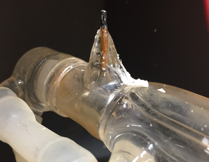
The investigation began at the power supply for the laser, but that didn’t yield any answers. Next he moved to the tube itself, noticing that the wire connection to the tube’s anode wasn’t soldered. The anode is an unknown material he suspects to be graphite and he found a video showing the “soldering” process for connecting a wire. (We added quotes to that as the video he linked doesn’t actually solder anything but the wrapped wire strands themselves.) The solution he found is a great tip to take away from the story. It’s a socket by TE Connectivity to which he soldered the wire. Assuming it’s power rated for the task, and won’t fall off during normal operation, this is a great way to do it.
But we digress. Even with the connection made, the old tube had to be replaced with a new one. It’s also notable that the portion of that anode inside the bad tube is orange in color when a new tube would be black like the part on the outside. Does this hint at why that tube died, and could this have been avoided? If you have insight, help us learn from this failure by leaving a comment below.


The anode is probably tungsten.
Looking at the pictures I would guess that the anode had a bad connection with the metal ring which resulted in arcing between the two (which would explain the orange deposits from the anode) and that the arcing caused local heating which probably cracked the tube thereby rendering it kaput.
Got a link to an ebay tube with the same orange anode, unused. https://www.ebay.com/i/123085591606?chn=ps
That’s not the culprit.
The orange is actually a sealing alloy that has the same thermal expansion/contraction and wetting characteristics as glass.
nvm I seethe orange you are talking about.
The new tube has the same Dumet seal wire color as the old one. I suspect it’s as simple as the old connector failed, arced, and overheated the lead in on the anode causing a micro-crack in the seal ruining the tube.
It’s orange inside the glass because it’s a dumet-seal or similar.
A couple of observations from a user of several “Cheap Chinese Lasers”.
First, most if not all HV connections on the tubes are just wrapped around the posts. This is not uncommon, nor a usual point of failure.
Second, the tubes shipped with the “k40” type lasers are known to be cheap, are usually not a true 40 watt tube and therefore usually over driven which result in an early demise.
For the connection I would have went for immediate gratification and just used an alligator clip.
It will take you a while, but eventually you will rid this world of OCD.
I would have gone with a screw terminal block if I am in a hurry. A crimped connection might be better as the pin might get hot due to heat from the laser tube.
Step 1: Find one of the lab glassware wizards of yore
Step 2: Find a Necromancer.
Step 3: ???
Step 4: Profit.
Ooops, beyond the snark, meant to include that I think the venerable SAMS laser FAQ has some hints for reviving laser tubes.
If the connection is overheating (causing the crack), maybe it’s time to look for a way of removing the heat with a large heat sink. More the mass of the heat sink more heat absorbed and removed from the problem. Just thinking out loud here. My bet would be the Alligator clip idea would be a bad one, only because there is only a small surface of metal touching the lead, therefore only a small amount of heat being able to be removed… You need a ‘Tim Taylor’ way of removing the heat, meaning big heat sink, and a large contact surface between the probe and the wire..
But first…
Tim Taylor would try liquid Nitrogen!
The tube is borosilicate glass, so it won’t be a Dumet wire seal, which are only used with soda-lime (soft) glass. It’s most likely tungsten, which gives that color. Also explains the difficulty in soldering to it.
Failure mode: Mad in China
Getting a conductor through a glass envelope is an engineering challenge of past days.
The conductor has to have the following properties –
1) Seals to glass (obviously)
2) Doesn’t oxidize so that the oxidization doesn’t wick through the seal and cause gas displacement (leaking)
3) Have an expansion coefficient close to glass so the seal doesn’t rupture with temperature changes
4) non-porous
The obvious solution would be a noble metal with a similar expansion coefficient to glass – a look across the periodic table and bingo the perfect noble metal is platinum. Won’t oxidize, seals to glass, non-porous and the right thermal expansion coefficient. You probably wont be getting platinum from cost cutting China.
The next best thing tried is nickel-iron alloys as they can be mixed to achieve the required thermal expansion coefficient.
However nickle-iron alloys have the following problems –
1) It’s porous especially when there are impurities in the alloy
2) It causes bubbles when sealing to glass and these bubbles create potential stress (fracture) points so it’s not suitable for high temperature vacuum tubes.
3) Doesn’t seal to glass well so it will not last for longer periods.
The next refinement was to coat the nickle-iron alloy with a copper tube. Copper has the completely wrong temperature coefficient for glass but seals well to glass, doesn’t cause bubbles when sealing to glass, doesn’t oxidize when sealed to glass, isn’t porous and is a far better conductor for higher power applications.
The dimensions of the nickle-iron alloy and the copper tube are chosen so that nickle-iron alloy provides the temperature coefficient and the copper conforms to the expansion / contraction under stress.
Getting these dimension right is quite a complex formula and this failure has resulted from the inclusion of the three variables below –
1) OMG: The expense of copper
2) WTF: The far lower expense of nickel-iron alloy
3) Cost –: Made in China
The excessive carbon on the remaining part of the contact point also suggest that the nickle-iron alloy was of a very low quality as well. Perhaps it was actually nickle-carbon-steel alloy alloy.
With a new tube, if your going to use a non-soldered connection then it has to have sufficient clamping force and mechanical support to avoid vibration and sufficient surface area of contact.
Any arcing will quickly carbonize the electrode.
The conductor is probably tungsten – I’ve seen tungsten/borosilicate seals before, and they have that color. Copper seals (e.g. Dumet, or copper-plated Kovar or Fernico) are much redder, and seals to plain Kovar/Fernico are gray.
IMO, you can’t necessarily assume heavier metals are non-porous when it comes to lighter gases. If you build a lattice of basketballs, you can still fire pingpong balls through it.
I’ve been using a China laser for many years.
Short laser tube life is almost always contributed to too high of a power setting.
100% power setting will highly shorten the life I’d the tube. It will actually cut better in the 65-85% setting. It took me years (and about 3 100w tubes) to learn this lesson! Do a test grid!
The 3 lasers I use all run at 75% max
Steve- Does running the laser at as low a power as possible have an effect on the tubes life as long as you stay out of the higher end of the power range? My cutter has an analog meter on it and it has been suggested that 20 mils is 100% and I rarely have mine peaking above about 5 on the meter. The meter being analog is slow to respond so I figure the peaks are higher but the meter does a good job of showing you an average.
Also, do think you are better off working in vector or raster mode? In my head I go back and forth on this. In vector mode the laser is on continuously a lot so I can see it getting hotter. In raster mode it is switched on and off wicked fast and I can feel that being hard on the tube, though I am not quite sure how.
Thanks for you insights to extend the laser life!
A suggestion for making the connection – find a small spring with an internal diameter just less the the post, solder the wire to the spring and ‘twiddle’ the spring round and onto the post where it will hold itself.
Or try Wago spring-clamp connectors. The 221 series is glorious.
I’m the one with that broken tube :-).
I have used a good industrial chiller with that tube, carefully not overheating it, running it at max 22°C. I had not much control over the max current provided with the original (nanoN2) controller, so I have replaced the controller with a Cohesion Mini one (https://mcuoneclipse.com/2018/04/15/upgrading-a-laser-cutter-with-cohesion3d-mini-and-lcd/) where I limit the PWM to 80%. I believe I just had bad (or maybe medium) luck with that tube. I’m not a laser expert, but I noticed that the new tube showed a kind of purple color in the tube (the gas?) while the old tube did not show this (any more?). So it might be that the old tube lost the gas (leaking it out?). My thinking is that the tube arced at the anode side, but not sure to what exactly it arced. I’ll keep that old tube on the side for a while, maybe I can investigate this later on. But for now I’m happy with the replacement :-).
If you’re processing high volumes, I would recommend investing in a laser with a ceramic or metal laser tube. They last much, much longer and have faster pulse rates, so you can produce better quality even while processing at high speeds. They are more expensive, but worth it. Another thing to look for related to product life is the size of the motor. A smaller motor cant support a great deal of laser power.
Good luck!
Wow, a lot of wild-ass (and uninformed) speculation here!
Fortunately RÖB and imajeenyus (and a few others) got it right.
(1) The orange (copper COLOR) is the correct color when the glass fused to the metal pin. (There a two materials used that look very similar, and I don’t really which is common with laser tubes.)
(2) The dark color is the correct color for the part of the pin exposed to air. (It’s NOT graphite. Sheesh)
(3) To match the properties of the metal pin to seal to the glass (fusing, temperature coefficient, etc) a compromise is made: the result, unfortunately, is the pin is NOT readily solderable.
(4) Many tube manufacturers warn customer to NOT attempt to solder directly to the pin. (Of course there are many YouTube video that do a half-assed job attempting to solder. Who are you going to believe? The material engineers at the company that *made* the tube, or some guy in a garage trying out pump up his YouTube channel with lasers and cat videos?).
(5) Tube manufacturers suggest a mechanical contact. Either spring, clip, or screw contact.
(6) The heat shrink tubing shown in the repair is inadequate for the High-Voltage that fires the tube. (Typically around 20KV~25KV … depending on tube size [scales with length]). That’s what all the HV Silicone RTV was potted around the connection.
(7) Often the heat-shrink appears to work, but when you close the hood, you get an arc from the exposed connection to the metal chassis.
(a) Most power supplies are protected for brief arcs, but they can’t take that many hits.
(b) The K40 is notoriously poorly grounded, so you risk serious shock or death when the HV lead arcs to the chassis. Or zapping your electronics, unless you’ve beefed up the grounds.
(8) It was mentioned that the *inside* end of the pin did not appear to be soldered to the internal anode electrode. That makes sense. Just as the *outside* pin cannot be soldered, neither can the *inside* end. On some tubes I’ve seen, it’s a mechanical crimp connection. Others appear to be spot welded. Besides, I suspect the metal in the solder would “poison” the laser tube gas.
(9) There was mentioned made of a “purple” color inside the tube. I’m not sure if he is referring to the glowing gas (when the tube is activated). However if you observe a slight pink/violet/purple tint on the inside of the center bore (when the tube is not activated) that is the tell-tale sign of a better tube that has a *catalyst*. Often this in not present on 40W tubes, but is more common on higher wattage (80W, 100W, etc). The catalyst assist the CO (Carbon MONOxide) which is created during the lasing process, into rapidly recombining into CO2 (Carbon DIOxide) which is what we’re after. The more rapidly the CO2 can be recovered, the better the laser efficiency.
(10).Regarding tube life. Manufacturers warn that OVER-CURRENT is the primary cause of a short tube life. Some of our makerspace users insist on running every project at 100%, despite the fact that a lower power and slower speed often yield better results.
(11) We had two tube that failed early. We observed a definate darkening of the internal cathode electrode after just a few short months, and a parallel declined in tube output and beam quality. (A later “autoposy” revealed a mis-calibrated HV Power Supply was driving the tube 30% over the manufacturer spec. Ouch! Our replacement RECI tube is still in operation 5 years later.)
(12) I also suspect that the NUMBER if ignitions is related to tube life, since each ignition has a much higher voltage than the actual running voltage, and for with each of those events a nasty current spike ensues. Some higher end HVPS use a pre-ignition bias, that eases the ignition event, and improves the burn quality (especially for fine engraving vs general cutting). You really don’t have any say about the number of ignitions, but it’s something to think about in a shop where the production natuarally used a lot of pulses. One online project had a modulator that intentionally rapidly pulsed the laser, thinking that he was getting more power. Instead, he was getting more power during those excessive uncontrolled ignition events. Tube manufacturers recommend against this.
Thank you for the great info. To clarify, in #12, if you have a choice, you are better off tube wise to use a vector based approach rather than a raster based approach? That is if say you are making a sign with letters on it, turning the laser on and filling in all of the first letter and turning the laser off than moving on to the next letter, is better for the tube than scanning across the entire sign one line at a time and pulsing the laser on and off hundreds of times per line? The ignitions are harder on the tube than continuous operation?
(13). BTW, there have been reports, in some online forums, about using automotive anti-freeze added to the distilled coolant water. Even in dilute quantities, it was claimed, that some brands of antifreeze were too conductive and were affecting laser operation. Likely capacitive coupling thru the (slightly conductive) water jacket to the laser bore. Some even claimed this induced an internal tube arc. (I’d need more details to understand that.)
Remember you want DISTILLED water, not just “purified” water.