When we think of physics experiments, we tend to envision cavernous rooms filled with things like optical benches, huge coils in vacuum chambers, and rack after rack of amplifiers and data acquisition hardware. But it doesn’t have to be that way – you can actually perform laser interferometry with a single component and measure sub-micron displacements and more.
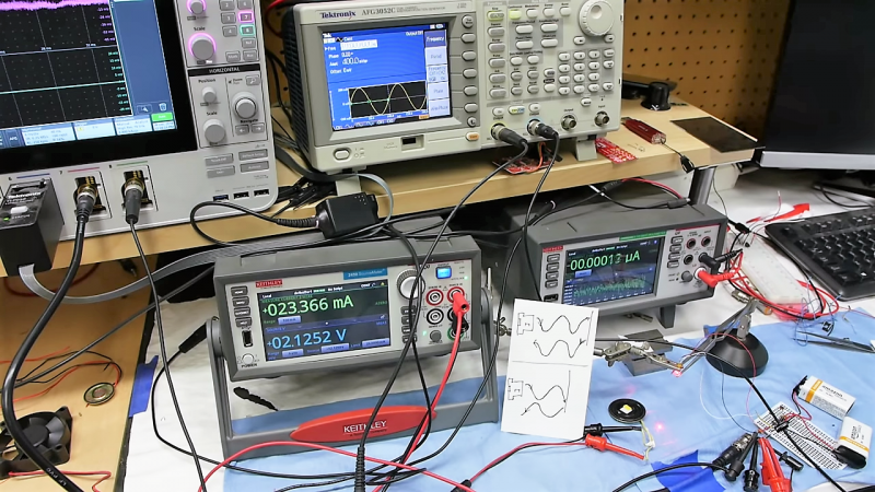
The astute viewer of [Ben Krasnow]’s video below will note that in order to use the one component, a laser diode, as an interferometer, he needed a whole bunch of support gear, like power supplies, a signal generator, and a really, really nice mixed-signal oscilloscope. But the principle of the experiment is the important bit, which uses a laser diode with a built-in monitoring photodiode. Brought out to a third lead, older laser diodes often used these photodiodes to control the light emitted by the laser junction. But they also respond to light reflected back into the laser diode, and thanks to constructive and destructive interference, can actually generate a signal that corresponds to very slight displacements of a reflector. [Ben] used it to measure the vibrations of a small speaker, the rotation of a motor shaft, and with a slight change in setup, to measure the range to a fixed target with sub-micron precision. It’s fascinating stuff, and the fact you can extract so much information from a single component is pretty cool.
We really like [Ben]’s style of presentation, and the interesting little nooks and crannies of physics that he finds a way to explore. He recently looked at how helium can kill a MEMS sensor, an equally fascinating topic.
[baldpower] sent in this tip. Thanks!


That is truly amazing. Ben is a genius. How does he come up with all these ideas?
By reading papers from people who did it first
“There is nothing new under the sun.”
But who cares, I’m not going to read those papers but I might learn something from Ben, even if YouTube is about the worst form of technical documentation outside of interpretive dance.
I think every video he’s ever made comes from reading papers from people who did it first.
The only thing Ben is doing is “videoizing” the paper to make it easier to absorb + share the paper.
Well, and recreating the paper/patent. That’s actually really hard in and of itself, and there’s no “just” to the quality and variety of his work.
Cool that it really is a laser interferometer. I was kind-of expecting the more common hack of driving a laser with a square wave and then just comparing the delay between transmitted and received pulses, which has a lot less resolution but seems easier to get working.
Do you have more info on the square wave thing?
I’d like to read more about that.
You can use correlation to get a really accurate measurement of a delay. But this interferometer is much better and can do sub-angstrom measurements (less than 0.1 nanometer) when everything is tuned up.
Pulsing the laser and measuring the delay is called LIDAR.
“When we think of physics experiments, we tend to envision cavernous rooms filled with things like optical benches, huge coils in vacuum chambers, and rack after rack of amplifiers and data acquisition hardware. ”
Citizen science…without the budget. :-d
” It’s fascinating stuff, and the fact you can extract so much information from a single component is pretty cool.”
Spy engineering.
I’d love to be in a place where “without budget” means easyly 50 grand worth of equipment on my desk…
+1
^this
Yeah, that gear is nice, especially the MSO, but what did he do that actually needed that expense? Any modern ‘scope could handle those measurements. Maybe recalling a stored trace for youtube demo purposes isn’t possible without a digital storage oscilloscope. Perhaps you cannot read uA on your DMM, but you don’t actually need to in order to do the interferometry – you just need to know enough about the expected current to build the trans-impedance amplifier.
Actually this is pretty clever but it was already exploited in the form of ECDL (external cavity laser diodes), except that the interfering return light was used to promote specific modes of the laser diode cavity or tune in a narrow wavelength
https://www.rp-photonics.com/external_cavity_diode_lasers.html
This trick can be used to tune in some CD burner laser diodes to some iodine cell transition at 440-ish nm, or with longer die laser diodes of visible spectrum to obtain the coherence length needed for holography
I wonder if one could couple red and green diodes to do SFG like in those yellow laser pointers based on OPO cut KTP
As a demonstration that is pretty cool. As a tool of any use there are holes you could drive a double decker bus through. The distance between the fringes isn’t 650nm, because it’s 650nm of *path length*, so it’s 325nm of movement. Light from a typical laser diode isn’t simply coherent, it has multiple linear modes (unless you have a very special diode) and modulating the current through the diode is going to cause mode hopping.
Genre ECDL ????
There are 2 batteries, one op-amp, resistors, capacitors, a laser led and ,mandatory here, a high accuracy lab power supply.
Which is the “One component” from the title ?
Anyway, very nice educational video.
Batteries are probably used, because as nice as desktop power supplies are, they do introduce noise into an electronic circuit. Normally there is not enough to worry about, but for sensitive amplifiers this can be enough to prevent proper operation. I work as a technician in a physics lab, and one of the student projects I was assisting with had to use batteries because the amplifiers were amplifying the noise from the modulated DC power supplies and outputting garbage. I now have two 12V DC batteries for use in case people need to power very sensitive student projects.
If you actually hook up a USB charger to an oscilloscope, you can see noise between 100KHz and 500 KHz due to the chopper circuits used in them.
In essence the batteries are a “signal cleanup” technique where noise is never introduced into a circuit to begin with..
I’m totally gonna try this at work next week.
Take a look at LT3045 and LT3094. Both are the lowest noise regulators currently available, which are as quiet as batteries.
This is brilliant.
I do recall yeas ago doing something not quite as complex with LED’s. A single LED was able to run as a light intensity monitor and was even sensitive enough to be able to detect near field objects. I stumbled on to this one while building a sensor array for a robot ad used it to detect walls etc.
The LED would emit light and a current sensor would detect how much current the LED was consuming, if an object was close there was a small change in the current consumption. The same thing goes for the light sensor. If an LED is running in sunlight there was a measurable change in current consumption that if it was being driven in the dark.
The purple interference waveform at about 12:04 looks like a sawtooth with the ramp on the leading side when the slope of the sinewave is negative and on the trailing side when slope is +. Wonder if the direction of the target’s motion could be inferred from this info and thus used to make a ring laser gyro by shining the led into a closed path with prisms or whatever.
‘Laser Inertial’ was just being developed by the USAF back in ’69. The INS sets I worked on were built by Litton and used mechanical gyros. Wonder if consumer-grade iINS’s could be developed with far superior CEP than the old-timey kind I worked on??
Ben says the puple wave measures the phase difference between emitted and reflected light.
All throughout the video I was wondering when Ben was going to say it himself, but he never did.
The interference pattern consits of vertical parts, where the phase flips sign, and of parts of the measured signal itself, in this case a sine wave. If you cut the signal on the phase flips and then shift the pieces vertically you have constructed your sinewave.
You can clearly see this on the the highes and lowest part of the sine wave. The purple trace has the same round form, and then the pieces get ever steeper.
This also implies of course that you can get a higher resolution by not just counting the phase flips, but also measuring the amplitude.
I had some trouble following Bens speach. Was distracted by his bench:
8 channel scope, Benchtop DMM that is jittering in the low pA range…
I don’t totally get how the signal is generated. If you take a look at the oscilloscope for example at 15:23 with the low frequency sine wave. The signal of the photodiode looks like a sine wave modulo 2pi, which is directly a measurement of the phase. However to get to this point with a common (e.g. Michelson interferometer) you have to do some phase shifting or some other phase reconstruction method since you can only measure the intensity of the light, not the phase! And there is only one photodiode (not three that would be required to do this).
So what is going on here??
Probably because of dopppler effects, slope of that purple trace is not symmetrical when speaker is going to diode vs when it is going away from diode. This way you can measure direction.
> However to get to this point with a common (e.g. Michelson interferometer) you have to do some phase shifting or some other phase reconstruction method.
That’s the beauty of this method. Laser is modulating itself and you can detect peaks and throughs of your laser wave. Counting them gives you displacement in half-wavelenghts. When [Ben] is talking, you can sometimes see oscillations from his speech affecting that speaker. Probably he has so much interference because everything is moving constantly because of nearby traffick.
This cannot be a doppler effekt. The laser photons are moving at speed of light. Compared to that the speaker isnt moving at all. Further a doppler effekt cannot explain the (mod 2pi) wrapping of the phase.
Some further consideration regarding the doppler measurment of the rotating motor shaft.
The shaft is rotating really slow (some 10 RMP) Lets assume the diameter is 10mm and it turns at 100 RMP.
This gives us a velocity at the surface of 2*Pi*0.005mm*100RPM/60sec = 0.05 m/s.
The speed of light is 299792458 m/s. The doppler shift will therefore be 0.05/c = 1.7e-10 of the Wavelength.
This is a wavelength shift of 1.7e-10 * 650 nm = 1e-16 m !!!!!!
It is impossible to see such a small difference in the oscilloscope.
Anyone have a part number for those laser diodes with the included photo detector?
No part number, but it’s quite common. All of the diodes I’ve scrounged from CD/DVD burners have had them inbuilt, for instance.
Sam seems to suggest that all diode lasers have photodiodes in: http://repairfaq.cis.upenn.edu/sam/laserdio.htm#diocss
Thanks for the reply. I was thinking that might be the case. I’ve never tried to salvage parts off of a CD/DVD burner, but I will now.
Also, thanks for the link.
Ben posted the datasheet, Googling ‘site:jameco.com 2120428.pdf’ gets the product:
https://www.jameco.com/z/LTLD505T-Lite-On-Electronics-Laser-Diode-650Nm-2-6VDC-Algalnp-Laser-Diode_2120428.html
Could anyone recommend a much better op-amp than the older TL082 that can also be use with a blu ray laser diode.