Turn Old Pinball Parts Into A Unique Digital Clock

It’s getting ever harder to build a truly unique digital clock. From electronic displays to the flip-dots and flip-cards, everything seems to have been done to death. But this pinball scoring reel clock manages to keep the unique clock ball in play, as it were.

It’s not entirely clear whom to credit with this build, but the article was written by [Lucky]. Nor do they mention which pinball machine gave up its electromechanical scoring display for the build. Our guess would be a machine from the ’60s, before the era of score inflation that required more than the four digits used. And indeed, the driver for the display is designed so that a scoring unit from any pinball machine from the electromechanical era can be used. An ESP8266 keeps the time with the help of an RTC and drives the coils of the scoring unit through a bunch of MOSFETs. The video below shows that it wouldn’t make a great clock for the nightstand; thankfully, it has a user-configured quiet time to limit the not inconsiderable noise to waking hours. It also flashes the date every half hour, rings solenoid operated chimes, and as a bonus, it can be used to keep score in a pinball game built right into the software.

We like the idea of honoring the old pinball machines with clock builds like this. We’ve seen a word clock built from the back-glass of an old machine, and one that uses a four-player back to display the date and alarm time too.

Continue reading “Turn Old Pinball Parts Into A Unique Digital Clock”

A Cheat Sheet For Publishing Python Packages

[Brendan Herger] was warned that the process of publishing a Python package would be challenging. He relishes a challenge, however, and so he went at it with gusto. The exhausting process led him to share a cheat sheet for publishing Python packages with the goal of making the next time smoother, while also letting other people benefit from his experience and get a running start.

[Brendan] describes publishing a Python package as “tying together many different solutions with brittle interchanges.” His cheat sheet takes the form of an ordered workflow for getting everything in place, with some important decisions and suggestions about things like formatting and continuous integration (CI) made up-front.

The guide is brief, but [Brendan] has made errors and hit dead ends in the hopes that others won’t have to. The whole thing came about from his work in deep learning, and his desire to create a package that allows rapid building and iterating on deep learning models.

Deep learning is a type of machine learning that involves finding representations in large amounts of data. [Brendan] used it in a project to automatically decide whether a Reddit post contains Star Wars plot spoilers, and we recently saw it featured in a method of capturing video footage only if a hummingbird is present.

How To Make A Pilotron, The Forgotten Tube

The vacuum tube is largely ignored in modern electronic design, save for a few audio applications such as guitar and headphone amps. The transistor is smaller, cheaper, and inordinately easier to manufacture. By comparison, showing us just how much goes into the manufacture of a tube, [glasslinger] decided to make a wire-element pilotron – from scratch!

To say this is an involved build is an understatement. Simply creating the glass tube itself takes significant time and skill. [glasslinger] shows off the skills of a master, however – steadily working through the initial construction, before showing off advanced techniques necessary to seal in electrodes, produce the delicate wire grid, and finally pull vacuum and seal the tube completely.

The project video is an hour long, and no detail is skipped. From 2% thoriated tungsten wire to annealing torches and grades of glass, it’s all there. It’s enough that an amateur could reproduce the results, given enough attempts and a complete shop of glassworking equipment.

The pilotron may be a forgotten design, but in 2018 it once again gets its day in the sun. Overall, it’s a testament to [glasslinger]’s skill and ability to be able to produce such a device that not only looks the part, but is fully functional on an electronic level, as well.

There’s a few people out there still building valves the old fashioned way, and we’d love to see more – tip ’em if you got ’em. Video after the break.

[Thanks to Morris for the tip!]

Continue reading “How To Make A Pilotron, The Forgotten Tube”

Every Computer Deserves A Rotary Encoder

In the era of touch screens and capacitive buttons, we’d be lying if we said we didn’t have the occasional pang of nostalgia for the good old days when interfacing with devices had a bit more heft to it. The physical clunk and snap of switches never seems to get old, and while you can always pick up a mechanical keyboard for your computer if you want to hear that beautiful staccato sound while firing off your angry Tweets, there’s a definite dearth of mechanical interface devices otherwise.

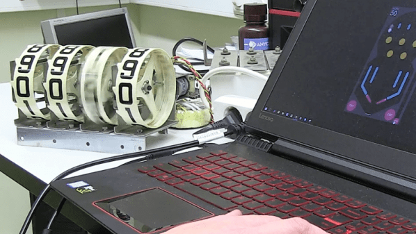
[Jeremy Cook] decided to take matters into his own hands (literally and figuratively) by designing his own multipurpose USB rotary input device. It’s not a replacement for the mouse or keyboard, but a third pillar of the desktop which offers a unique way of controlling software. It’s naturally suited to controlling things like volume or any other variable which would benefit from some fine tuning, but as demonstrated in the video after the break even has some gaming applications. No doubt the good readers of Hackaday could think of even more potential applications for a gadget like this.

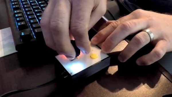
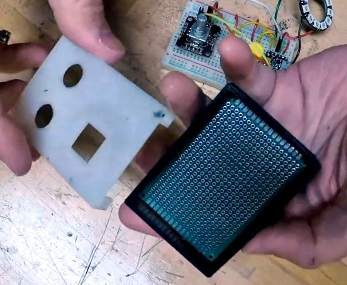
The device is built around the diminutive Arduino-compatible PICO board by MellBell, which features a ATmega32u4 and native USB. This allowed him to very rapidly spin up a USB Human Interface Device (HID) with minimal headaches, all he had to do was hang his buttons and rotary encoder on the PICO’s digital pins. To that end, he [Jeremy] used the fantastic I2C rotary encoder designed by [fattore.saimon], which readers may remember as a finalist in the Open Hardware Design Challenge phase of the 2018 Hackaday Prize. He also added a NeoPixel ring around the encoder to use for some visual feedback and because, well, it just looks cool.

Since all of the core components are digital, there’s not a whole lot required in the way of wiring or passive components. This let [Jeremy] put the whole thing together on a piece of perfboard, freeing him up to spend time designing the 3D printed enclosure complete with translucent lid so he can see the NeoPixel blinkenlights. He got the tolerances tight enough that the whole device can be neatly press-fit together, and even thought to add holes in the bottom of the case so he could push the perfboard back out if he needed to down the line.

[Jeremy] spends a good chunk of the video going over the software setup and development of the firmware, and details some of the nuances he had to wrap his head around when working with the I2C encoder. He also explains the math involved in getting his encoder to emulate a mouse cursor moving in a circle, which he thinks could be useful when emulating games that originally used an encoder such as Tempest or Pong.

We’ve seen similar USB “knobs” in the past for controlling volume, but the additional inputs that [Jeremy] built into his version definitely makes it a bit more practical. Of course we’re suckers for interesting USB input devices to begin with.

Continue reading “Every Computer Deserves A Rotary Encoder”

The Battle Between Robot Harmonica And Machine Finger Rages On

When asking the question “Do humans dream of machines?”, it’s natural to think of the feverish excitement ahead of an iPhone or Playstation launch, followed by lines around the block of enthusiastic campers, eager to get their hands on the latest hardware as soon as is humanly possible. However, it’s also the title of an art piece by [Jonghong Park], and is deserving of further contemplation. (Video after the break.)

The art piece consists of a series of eight tiny harmonicas, which are in turn, played by eight fans, which appear to have been cribbed from a low-power graphics card design. Each harmonica in turn has a microphone fitted, which, when it picks up a loud enough signal, causes an Arduino Nano to actuate a mechanical finger which slows the fan down until the noise stops. It’s the mechanical equivalent of a stern look from a parent to a noisy child. Then, the cycle begins again.

The build is very much of the type we see in the art world – put together as simply as possible, with eight Arduinos running the eight harmonicas, whereas an engineering approach may focus more on efficiency and cost. Between the squeaks from the toy harmonicas and the noise from the servos entrusted to quiet them, the machine makes quite the mechanical racket. [Jonghong] indicates that the piece speaks to the interaction of machine (robot harmonica) and humanity (the finger which quells the noise).

It’s a tidily executed build which would be at home in any modern art gallery. It recalls memories of another such installation, which combines fans and lasers into a musical machine. Continue reading “The Battle Between Robot Harmonica And Machine Finger Rages On”

Jeremy Hong: Weaponizing The Radio Spectrum

Jeremy Hong knows a secret or two about things you shouldn’t do with radio frequency (RF), but he’s not sharing.

That seems an odd foundation upon which to build one’s 2018 Hackaday Superconference talk, but it’s for good reason. Jeremy knows how to do things like build GPS and radar jammers, which are federal crimes. Even he hasn’t put his knowledge to practical use, having built only devices that never actually emitted any RF.

So what does one talk about when circumspection is the order of the day? As it turns out, quite a lot. Jeremy focused on how the military leverages the power of radio frequency jamming to turn the tables on enemies, and how civilian police forces are fielding electronic countermeasures as well. It’s interesting stuff, and Jeremy proved to be an engaging guide on a whirlwind tour into the world of electronic warfare.
Continue reading “Jeremy Hong: Weaponizing The Radio Spectrum”

Tiny Art Etched Into Silicon Wafers With Electron Beam Lithography

Looks like [Sam Zeloof] got bored on his Thanksgiving break, and things got a little weird in his garage. Of course when your garage contains a scanning electron microscope, the definition of weird can include experimenting with electron-beam lithography, resulting in tiny images etched into silicon.

You’ll probably remember [Sam] from his 2018 Hackaday Superconference talk on his DIY semiconductor fab lab, which he used to create a real integrated circuit. That chip, a PMOS dual-channel differential amp, was produced by photolithography using a modified DLP projector. Photolithography imposes limits to how small a feature can be created on silicon, based on the wavelength of light.

[Sam] is now looking into using the electron beam of his SEM as a sort of CNC laser engraver to produce much finer features. The process involves spin-coating silicon wafers with SU-8, an epoxy photoresist normally used with UV light but that also turns out to be sensitive to electron beams. He had to modify his SEM to control the X- and Y-axis deflection with a 12-bit DAC and provide a custom beam blanker. With a coated wafer in the vacuum chamber, standard laser engraving software generates the G-code to trace his test images on the resist. A very quick dip in acetone develops the exposed chip.

[Sam] says these first test images are not too dainty; the bears are about 2.5 mm high, and the line width is about 10 μm. His system is currently capable of resolving down to 100 nm, while commercial electron beam lithography can get down to 5 nm or so. He says that adding a Faraday cage to the setup might help him get there. Sounds like a project for Christmas break.

Continue reading “Tiny Art Etched Into Silicon Wafers With Electron Beam Lithography”