The only question we have about [mitxela]’s DIY vector graphics game console is: Why did he wait five years to tell the world about it?
Judging by the projects we’ve seen before, from his tiny LED earrings to cramming a MIDI synthesizer into both a DIN plug and later a USB plug, [mitxela] likes a challenge. And while those projects were underway, the game console you’ll see in the video below was sitting on the shelf, hidden away from the world. That’s a shame, because this is quite a build.
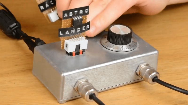
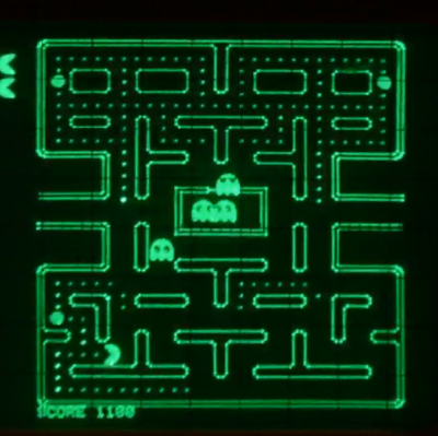 Using a CRT oscilloscope in X-Y mode as a vector display, the console faithfully reproduces some classic games, most of which, curiously enough, were not originally vector games. There are implementations of the Anaconda, RetroRacer, and AstroLander minigames from Timesplitter 2. There are also versions of Pac-Man, Tetris, and even Super Mario Brothers. Most of the games were prototyped in JavaScript before being translated into assembly and placed onto EEPROM external cartridges, to be read by the ATMega128 inside the console. Sound and music are generated using the ATMega’s hardware timers, with a little help from a reverse-biased transistor for white noise and a few op-amps.
From someone who claims to have known little about electronics at the beginning of the project, this is pretty impressive stuff. Our only quibbles are the delay in telling us about it, and the lack of an Asteroids implementation. The former is forgivable, though, because the documentation is so thorough and the project is so cool. The latter? Well, one can hope.
Thanks to [Keith Fulkerson] for the heads up on this one.


Cool build! I wonder if the output could be done with ilda, and (RGB) lazer for giant sky projected snake games.
I wondered if this could drive a Vectrex display, but the idea of a playing Snake on the underside of a low deck of clouds is pretty intriguing too.
The inconvenience of staying away from flight lines and having to notify and get permission from the FAA would make that a lot of trouble.
Probably not. But maybe with a laser.
Normal Galvometers used in laser projectors are way slower than what the oscope can do in X/Y mode. Most laser show software packages also do a lot of optimization when it comes to modulation of the laser diodes. There are faster scanners coming out (sort of) but at a $2500 price point.
speechless…
This is awsome. Back in the 80’s we progranned an HP SBC to write text on an oscilloscope but this is so much better. One thing I have done is instead of an oscilloscope, used a signal to drive the X and Y axis on an old CRT TV. Not sure if this would work in this situation. The audio portion of this sounds like a good building block for replicating a SID chip.
Very cool.
[mitxela] says in the video that the DACs are dissapointingly slow, with slow slew rates limiting the amount that can be drawn on screen. But seriously, it looks like he’s getting plenty of information on the screen anyway. In fact, a limited slew rate is probably the best thing for this kind of application, since DACs that are too fast will just end up drawing dots on the screen. Of course, the other down side of limited slew rate is that it means that if you try to move the beam 4 points right and 2 points up, it will be drawn as 2 right, 2 up, followed by 2 right, 0 up, which isn’t helpful, either.
When I was at Tektronix, I saw how they solved this problem on some plug-ins with digital storage: they used fast DACs (well, fast for the day, which were either DAC-08 or MC1408), along with integrators to set the slew rate for each channel. Quite a bit more complicated, but they made a great picture. The way this worked was, a sample/hold circuit sampled the old value of the DAC, and the difference between the old and new values of the DAC were fed into an integrator, whose capacitor was selected to get to the target voltage in the time it took to get to the next sampling clock. Then, at the next clock, the integrator output was clamped to the new DAC value, and the cycle repeated. Like I said, complicated.
Was that Mega Man music on the “Retro Racer” cart?
Is awesome work. Now he needs static Christmas tree – no dont. Omega Race next? Lack of Asteroids is wrong. Space Invaders is also a retro must.
Well obviously when you are that good you don’t feel the need to brag about what you did the moment you make something. There is some benefit to being completely self directed and not seeking approval, you are more likely to cover uncharted territory.
Hi,
May I ask you if there is any chance to use it with glavo and laser xy projector please ?
Thank you very much
Have a great day,
Galvos wouldn’t be able to keep up well. Most are limited to 30k/points per second measured at 8 degrees scan angle projecting the ILDA 30k test pattern. Better ones can do 60k (Cambridge + good amps, at $2000+ cost or the Pangolin Saturns on MachDSP galvo amp which is more towards the $3000.) Just the scanners, no laser diodes or other mechanical.
It is possible to write games that work with laser projectors, but they need the be authored to work in with less information on screen and perhaps frame optimization to minimized hard corners.
Nobody likes a showoff. Unless it’s this guy. He earns all credit. Great job!
This is fantastic. I’m confused about his weekly deadlines, but some people are just fast I guess. The lack of flicker when displaying extremely complex scenes is what I find the most incredible. I’m well familiar with Vectrex, made a cartridge for it and coded a loader. Made 3loshnik (https://hackaday.com/2012/11/05/custom-circuit-drives-a-small-round-crt-display/) back in the day. Vector displays either have little detail or flicker terribly.
Perhaps this scope has a really nice slow fading phosphor. A thing of beauty.
I think the main difference is the speed the display can operate at. In the Vectrex, the CRT used magnetic deflection, which is inherently harder to get fast deflection speeds with, and the DACs in it were limited to a relatively low frequency to drive this. I don’t know exactly what that frequency was, but based on the TV technology that Vectrex used, the bandwidth limitation had to be in the tens of kilohertz, at best. [Mitxela]’s project uses an oscilloscope for its display, which uses electrostatic deflection, and generally can be driven in the megahertz range. It also helps that it uses a modern microcontroller with probably a 16 MHz or 20 MHz clock, compared with about 2 MHz for the 6809 used in the Vectrex.
Good point about electrostatic deflection, I did not think of that.
Re: CPU clock, it of course helps. But Vectrex has little hardware helpers, namely integrators that draw the beam between the endpoints, and a beam modulator which is a shift register that’s used for generating text almost as if it were a raster scan display. It’s easy to overflow its screen with stuff that draws properly with some CPU cycles to burn, but flickers unbearably.
I love the existential crisis narration at the end.
6:26 into video: “If you think that doing it this way is stupid, you’d be right.”
lovely design. i have to correct the article though. the game mentioned is called timesplitters 2 and includes a few arcade/retro gameremakes as hidden bonuses. astrolander being a remake of the famous lunar lander, which is actually a vector graphics game. coming by a working lunar lander cabinet is a marvellous experience because it is so much fun and no emulation can beat a proper vector display. cabinets with vector displays are dying out and so very hard to come by. i am lucky to be in possession of a vectrex, but i am not sure how long it will continue to work, but there is no comparison to the original lunar lander and a vectrex port only exists as homebrew… now someone just needs to remake one of those color vector displays the starwars arcade cabs had, that would be the shiznit.