It certainly seems as though it should be an easy enough project; all [Miguel De Andrade] wanted was to receive a notification when somebody was pressing his doorbell, and thought it would be a good project to get his feet wet in the wonderful world of ESP8266 hacking. But as fate would have it, not everything went according to plan. In the end he got it sorted out, but it’s an interesting look at how even the “easy” projects can call the gremlins out of hiding.
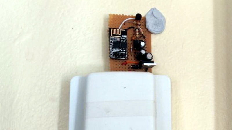
Arguably, the problems started when [Miguel] picked up an ESP-01 module from a local electronics retailer. While the convenience of buying the hardware in a brick and mortar store can’t be overstated, it did mean he was stuck with a slightly more spartan experience compared to the more common ESP “development boards”. Programming it externally with a Teensy ended up not being much of an obstacle, but it did mean he was stuck with only two GPIO pins.
At any rate, with ESP in hand, the next step was figuring out how the existing bell and intercom system even worked. Unfortunately, after some experimentation [Miguel] found there was a bit more going on there than he’d hoped. According to his multimeter, the one line from the intercom sits at approximately 5 VDC when it’s open, and drops down to 2.5 VDC when pressed. If that wasn’t bad enough, picking up the handset to answer the intercom sent the voltage up to a microcontroller-killing 12 VDC. To complicate maters further, the supply line for the intercom was 23 VAC, so he’d need to rectify that somehow if he wanted to avoid a separate power supply for the ESP.
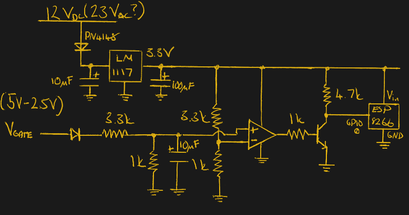 To turn this jumble of voltages into a nice clean 0 – 3.3 V signal for the ESP8266, he came up with a circuit based around the LM358 comparator that utilizes an LM117 regulator to power itself and the ESP at the same time. A couple of diodes are there to block the AC component from causing trouble, and an A2N2222A transistor is used as a buffer amplifier to boost the output of the comparator so it registers as a digital HIGH on the ESP. The circuit took a bit of fiddling to get sorted out, but in the end [Miguel] says it seems to get the job done.
You might think the problems were solved, but this is where it gets really annoying. The system would work fine for awhile, and then inexplicably go silent. In diagnosing the problem he realized that his circuit connected to GPIO_0 was inadvertently putting the ESP8266 into programming mode, since it was holding the pin LOW unless the intercom button was pressed. He assumed he could just move the circuit to the other GPIO pin, but as that one has the board’s LED on it, that caused its own problems. For now, [Miguel] hasn’t come up with a solution to this issue, and has learned to live with the fact that the system won’t come back up cleanly should it lose power for any reason.
If you’re looking for a slightly classier look than a scrap of perfboard stuck on the wall with what appears to be chewing gum, we’ve also seen the ESP8266 used in some more ornate doorbell setups. Of course if you still haven’t gotten your head wrapped around the whole Internet-connected button thing, you can always start with something a little easier.


This is even more complex in the USA. USA doorbells are usually 12VAC to a button in series with the chime. The chime can draw significant current when it is power (for example a mechanical bell). You can use a TRIAC to solve this problem, but it is not simple. Has someone previously designed a solution to this?
Put a AC input photocoupler (regular one might work too, I don’t know) across the button. When the button is not pressed current flows through the photocoupler and chime coil which turns the photocoupler on. When button is pressed the input to the photocoupler is shunted and the photocoupler turns off.
+1, that was my immediate thought.
The ESP has to also draw its power from the doorbell circuit.. How is the ESP going to get power both while the button is pushed and when it isn’t?
Use the trickle of current through the LED in the lighted button to charge a supercap.
Oh yeah…I was just focused on how to get the trigger from the doorbell button. Put an appropriate sized power resistor across the doorbell button and use the voltage drop across it to power the ESP. Small lipo battery to keep the ESP alive when its not getting doorbell power.
BTW, that’s exactly how lighted door bell buttons work, except it’s a light bulb in place of the photocoupler.
If they cut the electricity in your apartment when you ‘forget’ to pay the bill you can charge your phone with that current. At least if there’s an incandescent bulb in the button. Had to do it once.
That´s punk a.f.! :-)
Brings memories when I had to live in an unused toilet room at the campus for a couple of weeks during my college years as my employer went under and I really had no money to spare for dorm. It was the only room there not being hooked to the alarm.
Since it’s AC, some inductive coupling (or even a small transformer and a rectifier) might do the trick.
Not just in the USA. In Europe a “normal” door bell also usually operates at 10-14VAC, using a simple mains powered transformer and a button in series with a chime or bell.
Since the article on [Miguel]s system mentions intercom and handset I’m assuming he’s living in an apartment building with an intercom and a board of doorbells at the entrance, where you press the doorbell for whomever you want to visit, they pick up the intercom handset to ask who is there, you talk a bit, then they press a “door open” button to let you in. I’m assuming they have that sort of system in the US as well.
Isn’t that why you look at which pins don’t mess with boot functions…. spec sheets maybe… know which ones are actually interrupts, Rx/TX, i2c, etc… Also seems overly complicated.
Desolder the LED. Bam! Solved.
get a proper 8266 board (about $US2) and do it with that..
When I need several GPIOs, I use ESP12. But many times we need just one, and the temptation to use a ESP01 is big. I wonder why they put the GPIO02 and not GPIO04. But, that is what we have. The solution I found, is to solder a very tiny wire directly on the ESP8266 chip. GPIO04 and 05 are located on the corners of the chip, so I very bad solder like me can do it very easy. After that any epoxy glue will finish the job. I have like 10 ESP01 running in my house with this “hack”, and for me was the only bullet proof solution.
But if you want to stick to GPIO00 you can try some .1uF capacitor in series with the GPIO… should work
Brutish and clever, I like it.
I do something similar by connetcting GPIO16 to the RST pin in order to wake from the deep sleep. All in all I quite like the ESP01 and I use it a lot in my hacks.
OT: Sorry, I just pressed the “Report comment” on your coment by mistake. Hopefully they will not delete it…
To prevent it going into programming mode why not invert the input?
My doorbell uses a 12v transformer and bell that only receives power when the button is pressed (and the light burned out years ago).
So my thought is to use an ATTiny powered by small battery in sleep mode, wake-up when the doorbell is pressed, power-on the ESP module, send a message and go back to sleep.
Just throwing that out there.
I would love to see that solution. Also want to build something like this, but my background is software development and not electrical engineering, so I might (literally) burn myself.
Why not use gpio1 or gpio3?
This. The UART pins work just fine as GPIOs.
LM1117 Absolute Maximum Ratings, Input Voltage is 20V – a bit on the low side for the rectified 23V AC?
23RMS, so 35VDC real talk
Remove the transistor, so the signal sits high and goes low only when active. The ESP01 will still go into programming mode if it is power cycled while the button is pressed, but it’s a very simple mod.
Get rid of all the analog bits and the 2N2222 and replace them with a 74AHC132 Schmitt NAND. Gives you better cleanup of the input signal and enough logic to manage GPIO0 during power-up.
Hmm. Might need a PNP transistor cleaning up the input from the button to generate a detectable low by the schmitt.
Input goes through R to base of BJT. Diode from base to 3v3 to protect against 5V high input. E to 3V3. C via R to GND. Drive schmitt from the C-R junction.
I connected my ESP01 to a 3V lithium battery, assigned static IP, put a magnetic reed switch on the reset pin, and removed the power LED. Runs once then deep sleeps.
Could be nice to have the HaD community provides a solution here.
I am a software engineer, not electrical one, so I planned to do it fully digital with a RPi/BBB but would love to see this resolved.
So gents, go help Miguel ;)