Simple Circuit Keeps Process Control Loops In Tune

Spare a moment’s pity for the process engineer, whose job it is to keep industrial automation running no matter what. These poor souls seem to be forever on call, fielding panicked requests to come to the factory floor whenever the line goes down. Day or night, weekends, vacations, whatever — when it breaks, the process engineer jumps.

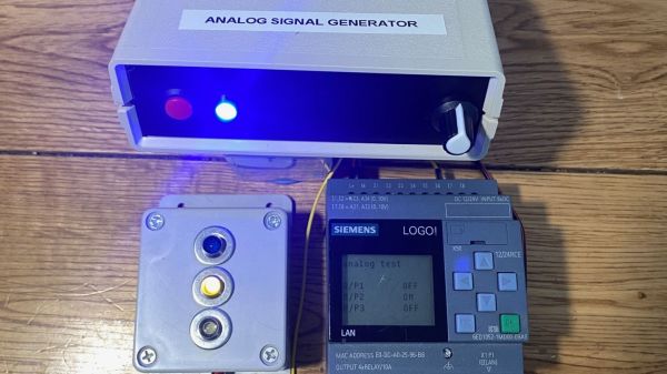
The pressures of such a gig can be enormous, and seem to have weighed on [Tom Goff] enough that he spent a weekend building a junk bin analog signal generator to replace a loop calibrator that he misplaced. Two process control signaling schemes were to be supported — the 0 to 10 VDC analog signal, and the venerable 4-20 mA current loop. All that’s needed for both outputs is an Arduino and an LM358 dual op-amp, plus a few support components. The 0-10 V signal starts as a PWM output from the Arduino, with its 0-5 V average amplified by one of the op-amps set up as a non-inverting amp with a gain of 2. With a little filtering, the voltage output is pretty stable, and swings nicely through the desired range — see the video below for that.

The current loop output is only slightly more complicated. An identical circuit on a separate Arduino output generates the same 10 V max output, but a code change limits the low end of the range to 1 V. This output of the op-amp is fed through a 500-Ω trimmer pot, and the magic of Ohm’s Law results in a 4-20 mA current. The circuit lives on a piece of perf board in a small enclosure and does the job it was built for — nothing fancy needed.

And spoiler alert: [Tom] found the missing loop calibrator — after he built this, of course. Isn’t that always the way?

Continue reading “Simple Circuit Keeps Process Control Loops In Tune”

Detail of a circuit sculpture in the shape of a lighthouse

Op Amp Contest: This Lighthouse Sculpture Flickers In The Rhythm Of Chaos

Op amps are typically used to build signal processing circuits like amplifiers, integrators and oscillators. Their functionality can be described by mathematical formulas that have a single, well-defined solution. However, not every circuit is so well-behaved, as Leon Chua famously showed in the early 1980s: if you make a circuit with three reactive elements and a non-linear component, the resulting oscillation will be chaotic. Every cycle of the output will be slightly different from its predecessors, and the circuit might flip back and forth between different frequencies.

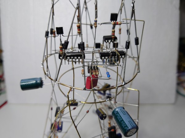
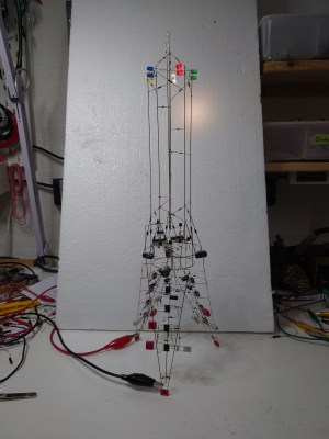
A circuit sculpture in the shape of a lighthouseA light modulated with a chaotic signal will appear to flicker like a candleflame, which is the effect [MaBe42] was looking for when he built a lighthouse-shaped circuit sculpture. Its five differently-colored LEDs are driven by a circuit known as Sprott’s chaotic jerk circuit. A “jerk”, in this context, is the third-order derivative of a variable with respect to time – accordingly, the circuit uses three RC integrators to implement its differential equation, along with a diode to provide nonlinearity.

The lighthouse has three chaotic oscillators, one in each of its legs. Their outputs are used to drive simple pulse-width modulators that power the LEDs in the top of the tower. [MaBe42] used the classic LM358 op amp for most of the circuits, along with 1N4148 diodes where possible and 1N4004s where needed – not for their higher power rating, but for their stronger leads. As is common in circuit sculptures, the electronic components are also part of the tower’s structure, and it needs to be quite sturdy to support its 46 cm height.

[MaBe42] used 3D printed jigs to help in assembling the various segments, testing each circuit before integrating it into the overall structure. The end result is a beautiful ornament for any electronics lab: a wireframe structure with free-hanging electronic components and randomly flickering lights on top. Want to learn more about circuit sculpture? Check out this great talk from Remoticon 2020.

Continue reading “Op Amp Contest: This Lighthouse Sculpture Flickers In The Rhythm Of Chaos”

Surface Mount Breathing Light PCB, using LM358 op-amp

Surface-Mount Light Breathes Life Into Your Project

If you’ve ever seen those gadgets with the “breathing light” LEDs on them and wondered how to do it, then [DIY GUY Chris] can show you how to design your own surface-mount version, using only analogue electronics.

Simulation trace showing the LED breathing light circuit operating. Traces for voltage and current are shown over a few seconds
The LED current tracks up and down in an approximately triangular-wave pattern

The circuit itself is built around a slow triangular-wave oscillator, that ramps the current up and down in the LEDs to make it look as if the lights are breathing in and out. The overall effect is rather pleasing, and the oscillation speed can be adjusted using the on-board potentiometer.

This project is actually an update to a previous version that used through-hole components (also shown in the video below), and goes to show that revisiting completed projects can give them a new lease of life. It also shows how easy it has become to design and order custom circuit boards these days. It’s not so long ago that a project like this would have been either made on stripboard or etched from copper-plated FR4 in a bubbling tank of acid!

If you have revisited an old project that you’re proud of and would like to show others, why not drop us a message on our tips line?

We have covered some other options for breathing LEDs in the past, such as this digital logic version, and this Arduino library that has a host of other effects to choose from, too. Continue reading “Surface-Mount Light Breathes Life Into Your Project”

Actuator Opens The Door To Drier Dishes

Dishwashers are great at washing dishes and even rinsing them, most of the time. Where they tend to fail is in the drying part. Somehow these things dry hot enough to warp stoneware dishes, but not so well that things are actually dry when you open the door. Blame it on the lack of air movement.

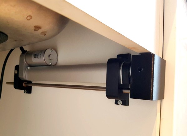
Ideally, the dishwasher cycle is started soon after dinner time so it can be finished and opened up before it’s time for bed. But if you do that, then you miss all the dishes from late-night snacking and the occasional wine glass. Wait until bedtime to start it, and it has to sit several hours with moisture inside. Obviously, the answer is to listen for the victory beeps at the end of the cycle, and use a slow but forceful actuator to push the door open.

[Ivan Stepaniuk] is listening for the dishwasher’s frequencies with a microphone, amplifying them with a trusty LM386, and using an STM32 blue pill to crunch the audio. [Ivan] has plans to incorporate an ESP8266 board for IoT, presumably to get a notification when the door has been opened successfully. Check out the demo after the break.

Yes, dishwashers are great until they aren’t, and some little part breaks. But why pay for a new detergent compartment cover when you can just print one?

Continue reading “Actuator Opens The Door To Drier Dishes”

The Swiss Army Knife Of Bench Tools

[splat238] had a ton of spare sensors laying around that he had either bought for a separate project or on an impulse buy, so he knew he had to do something with them. He decided to build his own digital multi-tool focusing on sensors that would be particularly useful in a workshop setting. Coincidentally, he was inspired by a previous hack that we covered a while back.

He’s equipped his device with a bubble level, tachometer, IR thermometer, protractor, laser pointer, and many, many more features that would make great additions to any hacker’s workspace. There’s a good summary of each sensor, making his Instructable somewhat of a quick guide to common sensing modalities for hardware designers. The tachometer, thermometer, laser pointer, and a few other capabilities are notable upgrades from the project we highlighted previously. We also appreciate the bigger display, allowing for more detailed user feedback particularly in using the compass and bullseye digital level among other features.

The number of components in [splat238’s] build is too extensive to detail one-by-one in this article, so please see his Instructable linked above for all the details. [splat238] made his own PCB for mounting each sensor and did a good job making the design modular so you wouldn’t need to add certain components if you don’t need them. Most of the components take some through-hole soldering with only a handful of 0805 resistors required otherwise. The housing was designed such that the user can handle the tool with one hand and can switch between each function with a push of a button.

Finally, the device is powered using a rechargeable lithium-polymer battery making it very reusable. And, if there weren’t enough features already, the battery can be charged via USB or through two solar panels mounted into the housing unit. Okay, solar charging might be a case of featuritis, but still a cool build either way.

Check out some other handy DIY tools on Hackaday.

Continue reading “The Swiss Army Knife Of Bench Tools”

A Simple Yet Feature-Packed Programmable DC Load

If you’ve got the hankering to own a lab full of high-end gear but your budget is groaning in protest, rolling your own test equipment can be a great option. Not everything the complete shop needs is appropriate for a DIY version, of course, but a programmable DC load like this one is certainly within reach of most hackers.

This build comes to us courtesy of [Scott M. Baker], who does his usual top-notch job of documenting everything. There’s a longish video below that covers everything from design to testing, while the link above is a more succinct version of events. Either way, you’ll get treated to a good description of the design basics, which is essentially an op-amp controlling the gate of a MOSFET in proportion to the voltage across a current sense resistor. The final circuit adds bells and whistles, primarily in the form of triple MOSFETS and a small DAC to control the set-point. The DAC is driven by a Raspberry Pi, which also supports either an LCD or VFD display, an ADC for reading the voltage across the sense resistor, and a web interface for controlling the load remotely. [Scott]’s testing revealed a few problems, like a small discrepancy in the actual amperage reading caused by the offset voltage of the op-amp. The MOSFETs also got a bit toasty under a full load of 100 W; a larger heatsink allows him to push the load to 200 W without releasing the smoke.

We always enjoy [Dr. Baker]’s projects, particularly for the insight they provide on design decisions. Whether you want to upgrade the controller for a 40-year-old game console or giving a voice to an RC2014, you should check out his stuff.

Continue reading “A Simple Yet Feature-Packed Programmable DC Load”

Fail Of The Week: The Arduino Walkie That Won’t Talkie

There’s something seriously wrong with the Arduino walkie-talkie that [GreatScott!] built.

The idea is simple: build a wireless intercom so a group of motor scooter riders can talk in real-time. Yes, such products exist commercially, but that’s no fun at all. With a little ingenuity and a well-stocked parts bin, such a device should be easy to build on the cheap, right?

Apparently not. [GreatScott!] went with an Arduino-based design, partly due to familiarity with the microcontroller but also because it made the RF part of the project seemingly easier due to cheap and easily available nRF24 2.4 GHz audio streaming modules. Everything seems straightforward enough on the breadboard – an op-amp to boost the signal from the condenser mic, a somewhat low but presumably usable 16 kHz sampling rate for the ADC. The radio modules linked up, but the audio quality was heavily distorted.

[GreatScott!] assumed that the rat’s nest of jumpers on the breadboard was to blame, so he jumped right to a PCB build. It’s a logical step, but it seems like it might be where he went wrong, because the PCB version was even worse. We’d perhaps have isolated the issue with the breadboard circuit first; did the distortion come from the audio stage? Or perhaps did the digitization inject some distortion? Or could the distortion be coming from the RF stage? We’d want to answer a few questions like that before jumping to a final design.

We love that [GreatScott!] has no issue with posting his failures – we’ve covered his suboptimal CPU handwarmer, and his 3D-printed BLDC motor stator was a flop too. It’s always nice to post mortem these things to avoid a similar fate.

Continue reading “Fail Of The Week: The Arduino Walkie That Won’t Talkie”