[Big Clive] picked up some chip-on-board (COB) LEDs meant for hydroponics that were very unusual and set out to examine them on video. Despite damaging the board almost right away, he managed to do some testing on these arrays and you can see the results in the video below. He also compares it to older LED modules.
The 144 LEDs produce a lot of light. In addition to powering the device up, he also looks at the construction of the LEDs under a magnification, comparing the older style that used tiny bond wires to make connections versus the new version soldered on the board directly.
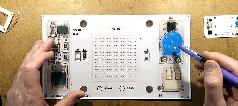
The right side of the board has an AC connection, a metal oxide varistor to prevent overvoltage, and a bridge rectifier. The other side contains an LED current sink circuit. [Clive] does a bit of math and decides that the LEDs are in an arrangement that lets you select if have clusters of LEDs to accept 220V input or 110V.
The devices in the current sink didn’t show up in an Internet search. [Clive] does a bit of probing and analysis to shed light on what’s happening in the circuit. There’s an IC, a Zener diode, and a beefy transistor.
Chip on board isn’t very new but it poses the same kind of problems for experimenters that surface mount once did. These appear to use the “flip” method where the boards have solder balls placed on them and rest on the inverted components as everything goes through an oven. In some cases, though, fine bond wires or ribbons are welded using a laser or ultrasonic methods in the same way that conventional ICs attach to their lead frames.
LED lighting sure has come a long way since 2014 or 2012. You have to wonder how long it will be before we see a Star Trek-style lighting panel.


Does anyone knows if those kind of COB modules with integrated drivers are dimmable?
Unless it’s sold as dimmable I’d say no.
Adding the electronics to be compatible with old triac “chop the AC” dimmers requires more and higher rated parts.
Not without bypassing the driver circuitry.
Did he even bother to measure the voltage and current the LED’s themselves were fed with both as a separate emitter and as a whole.
YT is acting funny again with my third-party YT viewer.
Looks like it’s just a matter of adding a potentiometer in series with the resistor that sets the current.
LED brightness is not linear with current limiting resistor. You could adjust variable resistor but the brightness would show very little noticeable fade until you get near the very low end of less than a few mA per LED before it’d darken.
PWM is the only way to obtain linear variable brightness.
That’s not exactly true. Most LED data sheets have a chart comparing forward current versus relative luminous flux. As far as this Cree XHP35 datasheet in front of me, it’s relatively linear from 0 mA to 1050 mA.
That’s not LEDs, that’s human vision. LED brightness is approximately just proportional to current.
How about an audio taper pot? depending on which side of the wiper you hook to, gives you a choice of the resistance curve.
Then there’s always the trick of opening the potentiometer shell and trimming the carbon track to affect the response
sheesh. How old was the book I read that tip in?
That is a bad idea. Dropping the intensity of a led with a resistor is wasteful of power. The wasted power also creates problems: heat that will need to go somewhere.
In the case at hand a 1M resistor was placed in series. This FOR SURE reduces the current to a safe level for that resistor: even with the leds behaving as a short the current would be low enough to be safe to handle for the resistor.
At 220k the power in the resistor could approach 1/4 W, the limit for normal sized resistors. (nowadays 1/8 is becoming more common). Any lower and you’re going over the limit for a standard resistor. Fixed value resistors you can get in higher power ratings. Potentiometers are difficult and expensive in higher power ratings.
Simply measuring the flicker rate might help determine the mystery chip’s functionality. It seems like the driver circuit ought to be relatively easy to map out, which would also probably yield the chip’s pinout.
“You have to wonder how long it will be before we see a Star Trek-style lighting panel.”
My apartment building is full of them. The old fluorescent ceiling light fixtures in the hallways here were recently replaced with LED fixtures that are less than 2 cm thick! Judging from a how a partially failed unit looks, I think that the LEDs are arranged around the perimeter of the fixture and some sort of diffusion/reflection system (possibly similar to the plastic sheets used in the backlights of LCD TVs) spreads the light evenly across and out the face of the panel. They’re very bright, they don’t flicker at all, and look very much like something out of Star Trek. They are quite an improvement over the old fixtures.
If you want to buy a Star Trek style lighting panel, they aren’t expensive: https://smile.amazon.com/4-Pack-Luxrite-Bright-Dimmable-Ceiling/dp/B01GEYUPA0/
Well, yeah, but the Star Trek ones were wireless and curiously lacked an off switch ;-)
Oh man, I didn’t realize the hero image was a print out. I was wondering why that capacitor was the size of a cookie.
Haha. Even in one of Clive’s vids he started probing the printout with the meter until he woke up and realised that that wouldn’t work – had a good laugh on that one.