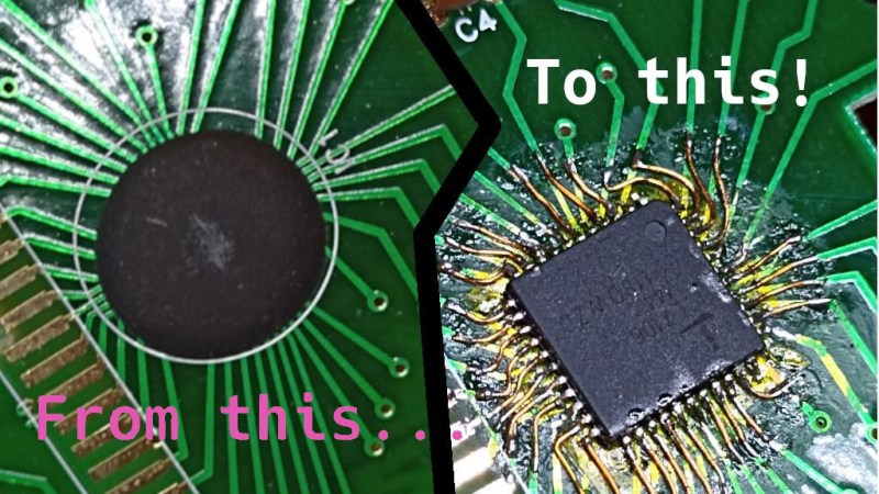
On the left, an image of a COB on the multimeter's PCB. On the right, a QFP IC soldered to the spot where a COB used to be, with pieces of magnet wire making connections from the QFP's pins to the PCB tracks.

Epoxy Blob Excised Out Of Broken Multimeter, Replaced With A QFP

The black blobs on cheap PCBs haunt those of us with a habit of taking things apart when they fail. There’s no part number to look up, no pinout to probe, and if magic smoke is released from the epoxy-buried silicon, the entire PCB is toast. That’s why it matters that [Throbscottle] shared his journey of repairing a vintage multimeter whose epoxy-covered single-chip-multimeter ICL7106 heart developed an internal reference fault. When a multimeter’s internal voltage reference goes, the meter naturally becomes useless. Cheaper multimeters, we bin, but this one arguably was worth reviving.

[Throbscottle] doesn’t just show what he accomplished, he also demonstrates exactly how he went through the process, in a way that we can learn to repeat it if ever needed. Instructions on removing the epoxy coating, isolating IC pins from shorting to newly uncovered tracks, matching pinouts between the COB (Chip On Board, the epoxy-covered silicon) and the QFP packages, carefully attaching wires to the board from the QFP’s legs, then checking the connections – he went out of his way to make the trick of this repair accessible to us. The Instructables UI doesn’t make it obvious, but there’s a large number of high-quality pictures for each step, too.

The multimeter measures once again and is back in [Throbscottle]’s arsenal. He’s got a prolific history of sharing his methods with hackers – as far back as 2011, we’ve covered his guide on reverse-engineering PCBs, a skillset that no doubt made this repair possible. This hack, in turn proves to us that, even when facing the void of an epoxy blob, we have a shot at repairing the thing. If you wonder why these black blobs plague all the cheap devices, here’s an intro.

We thank [electronoob] for sharing this with us!

big LED flashlight

Own The Night With This Ludicrously Bright DIY Flashlight

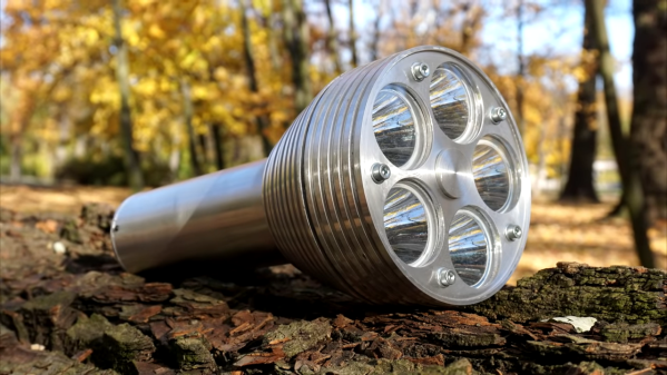
If you’re a flashlight person, you know that there’s little you would do to get the brightest, most powerful, most ridiculous flashlight possible. You might even decide to build yourself a ludicrously powerful flashlight, like [Maciej Nowak] did.

If you choose the DIY route, be warned that it’s probably not going to be a simple process, at least if you follow [Maciej]’s lead. His flashlight is machined out of aluminum rounds, all turned down on the lathe to form the head of the flashlight. The head is made from three parts, each of which acts as a heat sink for the five 20-Watt CREE XHP70 LED modules. The LEDs are mounted with care to thermal considerations, and wired in series to DC-DC converter that provides the necessary 30 V using a battery pack made from four 21700 Li-ion cells. The electronics, which also includes a BMS for charging the battery and a MOSFET switching module, form a tidy package that fits into the aluminum handle.

The video below shows that the flashlight is remarkably bright, with a nice, even field with no hotspots. Given the 45-minute useful life and the three-hour recharge time, it might have been nice to make it so anywhere from one to five of the LEDs could be turned on at once. Some interesting effects might be had from switching the LEDs on sequentially, too.

Given the proclivities of our community, it’s no surprise that this is hardly the first powerful flashlight we’ve seen. This one broke the 100-Watt barrier with a single COB LED, while this ammo-can version sports an even higher light output. Neither of them looks much like a traditional flashlight, though, which is where [Maciej]’s build has the edge.

Continue reading “Own The Night With This Ludicrously Bright DIY Flashlight”

COB LED Teardown

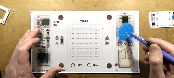
[Big Clive] picked up some chip-on-board (COB) LEDs meant for hydroponics that were very unusual and set out to examine them on video. Despite damaging the board almost right away, he managed to do some testing on these arrays and you can see the results in the video below. He also compares it to older LED modules.

The 144 LEDs produce a lot of light. In addition to powering the device up, he also looks at the construction of the LEDs under a magnification, comparing the older style that used tiny bond wires to make connections versus the new version soldered on the board directly.

Continue reading “COB LED Teardown”

Lessons In Disposable Design From A Cheap Blinky Ball

Planned obsolescence, as annoying as it is when you’re its victim, still has to be admired. You can’t help but stand in awe of the designer who somehow managed to optimize a product to live one day longer than its warranty period. Seriously, why is it always the next day?

The design of products that are never intended to live long enough to go obsolete must be similarly challenging, and [electronupdate] did a teardown of a cheap LED blinky toy to see what’s involved. You’ve no doubt seen these seizure-triggering silicone balls before, mostly at checkout counters and the like where they’re sold at prices many hundreds of times what it took to make them. This particular device, which seems representative of the species, has two bright LEDs, a small controller chip, a trio of button cells for power, and a springy switch to activate it. All this is mounted to a cheap scrap of phenolic resin PCB, with the controller chip and one of the LEDs covered by a blob of clear epoxy.

This teardown one-ups most others, as [electronupdate] disrobes the chip and points a microscope at the die; the video below shows just how few transistors are employed and proposes a likely circuit. Everything about this ball just oozes cheapness, and it’s likely these things cost essentially nothing to build. Which makes sense for something destined for the landfill within a week or so.

Yes, this annoying blinky-thing is low-end garbage, but there are still design lessons to be learned from it. Anything that’s built for a broad market has to be built to a price point, and understanding those constraints is important to understanding how planned obsolescence works.

Continue reading “Lessons In Disposable Design From A Cheap Blinky Ball”

Old LED Light Bulbs Give Up Filaments For Spider Web Clock

We love it when something common gets put to a new and unusual use, especially when it’s one of those, “Why didn’t I think of that?” situations. This digital clock with a suspended display is just such a thing.

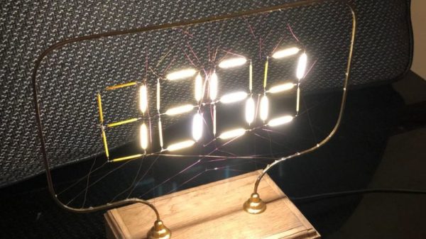
The common items in this case were “filaments” from LED light bulbs, those meant to mimic the look of clear-glass incandescent light bulbs. [Andypugh] had been looking at them with interest for a while, and realized they were perfect as the segments for a large digital clock. The frame of the clock was formed from bent brass U-channel and mounted to an oak base via turned stanchions. The seven-segment displays were laid out in the frame and the common anodes of the LED filaments were connected together, with the cathode for each connected to a very fine wire. Each wire was directed through a random hole in the frame and channeled down into the base, to be hooked to one of the four DS8880 VFD driver chips. The anode wires form a lacy filigree behind the segments, which catch the light and make then look a little like a spider’s web. It looks great, but nicht für der gefingerpoken – the frame is at 80 VDC to drive the LED segments. The clock is synced to the UK atomic clock with a 60-kHz radio link; see the long, painful sync process in the video below.

We like the open frame look, which we’ve seen before with an equally dangerous sculptural nixie clock. And this gives us some ideas for what to do with those filament LEDs other than turning them back into a light bulb. And if [Andy] sounds familiar, it could be because he’s appeared here before. First of all resurrecting the parts bin for an entire classic motorcycle marque, and then as the designer of SMIDSY, a robot competitor in the first incarnation of the UK Robot Wars series.

Continue reading “Old LED Light Bulbs Give Up Filaments For Spider Web Clock”

An Artsy And Functional LED Filament Lamp

Some projects end up being more objet d’art than objet d’utile, and we’re fine with that — hacks can be beautiful too. Some hacks manage both, though, like this study in silicon and gallium under glass that serves as a bright and beautiful desk lamp.

There’s no accounting for taste, of course, but we really like the way [commanderkull]’s LED filament lamp turned out, and it’s obvious that a fair amount of work went into it. Five COB filament strips were suspended from a lacy frame made of wire, which also supports the custom boost converter needed to raise the 12-volt input to the 60 volts needed by the filaments. The boost converter is based on the venerable 555 timer chip, which sits in the middle of the frame suspended by its splayed-out legs and support components. The wooden base sports a few big electrolytics and some hand-wound toroidal inductors, as well as the pot for adjusting the lamp’s brightness. The whole thing sits under a glass bell jar, which catches the light from the filaments and plays with it in a most appealing way.

There’s just something about that dead bug building technique that we love. We’ve seen it before — this potentially dangerous single-tube Nixie clock comes to mind — but we’d love to see it done more.

[via r/electronics]

A Look At Chinese Value Engineering

Seventy cents doesn’t buy you a lot these days. Maybe some sweets or candies at most. How about a string of LEDs that you can use to decorate your home during the festive season? [Amaldev] was curious to know what was, or wasn’t, inside these blinky LED strings which made them so cheap. He’s done a Christmas LED Light Teardown and shows how blinky LED string lights can be built with the bare minimum of components.

The string he purchased had 28 LEDs – seven each in four colors, a controller box with one push button and a  power cord. Without even knowing what is inside the controller box, the cost of the product seems astonishing based on this BoM. The single push button cycles through eight different light patterns for each press. It even has a faux CE mark for the supply plug. Cracking open the case, he finds that the controller board is sparsely populated with just seven through hole components and a COB (chip on board) module. A simple, 8-bit, 8-pin microcontroller is possibly what controls the device.

[Amaldev] sketches out a schematic to figure out how it works. There are two arms with 14 LEDs of alternating colors, each of which is controlled by an SCR. Two GPIO output pins from the COB control the gates of each of these SCR’s. The button is connected to a GPIO input, and a second input is connected to the AC supply via a current limiting resistor. Most likely, this is used to determine the zero crossing of the waveform so that the COB can generate the appropriate trigger signals for the gate outputs.

It is unlikely that these products are manufactured using automated processes. The PCB production could be automated, but soldering all the wires, fitting it all in the enclosure and preparing the LED string itself would require manual labor. At US$ 0.7 retail on the street, it is difficult to imagine the cost breakdown even when the quantities are in large numbers. Maybe a combination of cheap components, recycled or rejected parts (mains cord/enclosure), lack of safety and protection measures (no fuses, no strain reliefs) and reducing the component BoM to an absolute, bare minimum, coupled with very high volumes lets them pull it off? What are your thoughts – chime in with comments.