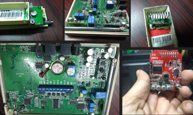
I have a home alarm system that has me wondering if I can make it better with my maker Kung-fu. Recently we had to replace our system, so I took the time to dissect the main controller, the remote sensors, and all the bits that make a home security system work.
To be precise, the subject of today’s interrogation is a Zicom brand Home Alarm that was quite famous a decade ago. It connects to a wired telephone line, takes inputs from motion, door, and gas sensors, and will make quite a racket if the system is tripped (which sometimes happened accidentally). Even though no circuits were harmed in the making of this post, I assure you that there are some interesting things that will raise an eyebrow or two. Lets take a look.
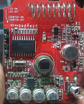
The Gateway of the Zicom Home Alarm System


The front panel is simple with a keyboard and an LCD display and a quick search on Aliexpress yields similar units still available. A number pad and a few other keys are the only way to configure the system to add sensors, set alerts, activate, and deactivate the alarm. Unfortunately there is no USB port to allow PC based configuration and the complicated process of using this gateway makes it rather user unfriendly.
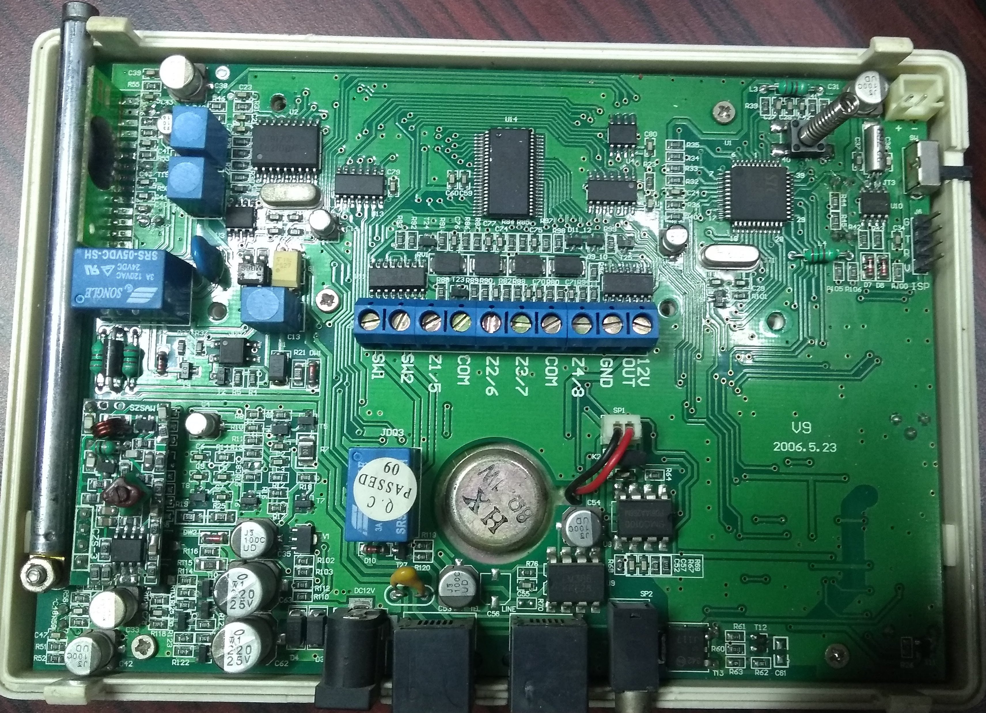
Under the hood, there is a lot of classic design work to be found. Here is a list of the most prominent looking blobs on the PCB inside.
-
[Microcontroller] [PDF]
-
24C18 EEPROM [blurry]
-
HT1380 – RTC (PDF)
-
LM339 – Comparator
-
HT1621B – LCD Driver (PDF)
-
74HC164B – SIPO
-
HT9170D – DTMF Receiver
-
SMC0100 PD61AA266M – Alarm Tone Generator?
-
LM380 – Audio Amp
-
ST HCF4052 – Analog Mux/Demux (PDF)
-


Lets start (guessing) from the top. The 8051 variant(1) is obvious and I guess handles the basic operations of the system. The EEPROM(2) is interesting and should be the place where the system stores configurations such as the phone numbers to be called and the ID of the sensors that have been paired with the system.
We also see a HT1380(3) serial RTC which exposes a serial interface and even though the 8051 variant does have a dedicated SPI peripheral, there are firmware tricks to bit bang effectively.
The controller should also be talking to the dedicated Holtek LCD Controller(5) via the 3 wire serial interface. Bit bang anyone? LM339s I found would be a good fit to buffer external inputs and 74HC164s serial-in-parallel-in chips are used to control wired alarms or control external relays and such.
The ST HCF4052 is an Analog Mux-Demux and was a bit of a surprise in an all digital system.


There is a DTMF decoder(7) which I assume is how a user would deactivate the alarm remotely by entering a code and then doing some other single digit commands. You don’t want your neighbors throwing rocks to silence a blaring alarm in your absence. The analog Mux-Demux could be used to switch the Decoder and dialing system to the phone lines, though relays are traditionally used for that task.
The RF part is interesting and uses what looks to be a hobby grade module which means that in order to snoop on the system, all you would need is an Arduino and a similar module. The funny thing is that the microcontroller is running at around 3 MHz and with a 6T/12T clock machine cycle. That puts the core at 250kHz in the worst case. The firmware would have to be pretty tightly knit. My guess is that the Timer/counter peripherals are used to count pulse widths from the RF modules and then pushed into a common buffer which is then read by the main routine and such.
The last part is the vertically soldered PCB with a custom chip inside. Any guesses?
Exploring the Door Sensor
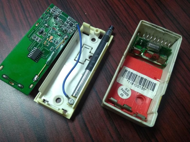
Since everything is 433MHz, the sensor nodes are simple little creatures that I guess, chirp every now and then. There is evidence of a small SOIC microcontroller on the door sensors, but the part number is not visible. A crystal suggests a smaller 8051 variant that supports lower power consumption waiting for a GPIO interrupt which would trigger the transmission. There is no receive module which means that getting an acknowledgement is out of the question and there would also be a code for sending a low battery alert.
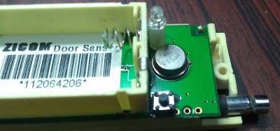
The R433A TO39[PDF] metal-can seen in the image is a SAW Resonator commonly found in AM Transmitter modules and the sensor of choice is a reed switch that provides the requisite interrupt to the microcontroller. Wax-on, wax-off. There is a write-up on The Mechanics of a Reed Switch that you may find useful.
There are no regulators so the two AAA cells provide 3.0V and below to power the system. Its simple and gets the job done.
The Motion Sensor
The motion sensor is more interesting, with a Toshiba TMP87P808 Microcontroller [PDF] in it. Personally, I’ve never used that part but a quick google search reveals that a bunch of companies in China use it and its relatives for lower power applications. Cool!
The sensing element is a Pyroelectric IR sensor[PDF] common in intrusion detection systems. There are variants available in the market with multiple sensor elements and other bells and whistles.
I was surprised at how low power the module was since it kept working for around 4 years on three AA batteries. The batteries leaked in one of the modules killing the PCB which adds to the list of lessons learned in my humble opinion.
An R433 SAW resonator powers the RF end of the device in the same fashion as the door sensor and typically it is also the most power hungry piece of the puzzle.
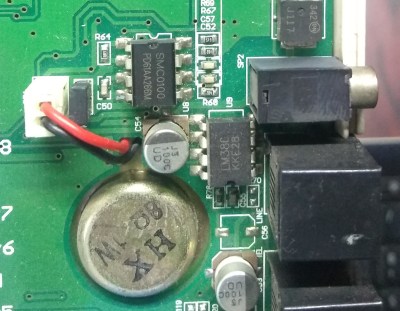
The Gas Sensor and Power Supply
The gas sensor we have is a wall plug type and is the largest of all the sensors in the lot and understandably so. Most gas sensors traditionally employed a sensor with a heating element inside and with great heat comes great power loss. A lot of these sensors can be purchased online at reasonable prices but special sensors such as O2 and special gas sensors are still uncommon. Mems sensors have come to replace these and are much more affordable while providing accuracy and efficiency hence the modern-day fire alarm’s small size.
In a country like India, where power cuts are common occurrence, it is important to have a backup power supply. The system came with a rather large wall-wart with a NiCd cells and a charging circuit along with a step down transformer. The output is a standard barrel jack and no way of telling the main system of the backup power levels.
The Alert Mechanism
In addition to the small speaker the system can talk to an external alarm buzzer which suggests that there is an AM transmitter module somewhere on the control module. Once triggered, the system will call a predefined phone number via a wired telephone line and then wait for the user to enter a code via DTMF.
That seems to be the extent of the connectivity and if someone were to cut the hardline (Matrix movies anyone?) the system would be stuck screaming until someone manually deactivates it or the power dies. We have had an interesting experience with a weather storm falsely triggering the system in the middle of the night with phone lines down and some angry neighbors. No rocks though.
Sniffing Wireless Communication
Using an SDR Dongle, it would be easy to snoop around the wireless transmissions. Batteries and a button press on the door sensor resulted in these transmissions which I am assuming contains the ID code as well as other pairing data for the sensor.


The same transmission happens six times after I press the button on the PCB. Typically RF 433 MHz sensors use line codes such as On-off keying, Manchester, or Biphase Mark. If the manufacturer follows standard protocols, it may be possible to use software such as rtl_433 or Universal Radio Hacker to automate the process somewhat. We have even seen the use of Matlab for reverse engineering this stuff.
This is one of the reasons why many commercial solutions would provide wired connections to their sensors. Alternatively, chips with rolling codes could be used as well but wired systems also come with the benefit of never having to change batteries. After all, motion sensors in a busy office would drain the cells more quickly than a sensor in a home.
Conclusion
This system is a decade old, and things have changed for the better but the principles are the same. The system is designed to be cost effective while delivering a certain level of service. It has its flaws but is a good learning point. With the information we have collected, it should be possible to design a custom solution which is exactly what I have done so stay tuned.


Keupad plastic housing makes it look like a derivative of a Napco system.
The mystery epoxy blob chip might be a sound playback chip for example “please input ddeactivation code” “code incorrect” style of prompts on the phoneline interface. Outside of that I would have figured it was the buzzer/alarm sound generator, but that’s handled by other chips.
(btw the new commenting system does not reacognize the .solutions TLD, like in ftg.bonk.solutions)
Nope! The only thing the unit did was an obnoxious wa-wa sound. Keep guessing. :)
Am I the only one thinking of the UA 571-C Automated Sentry Gun?
Nope, was also slightly disappointed this wasn’t the case.
If you have programming codes for this unit please mail saxenavinayk@gmail.com