
Just about everywhere you go, there’s a reed switch nearby that’s quietly going about its work. Reed switches are so ubiquitous that you’re probably never more than a few feet away from one at any given time, especially at home or in the car. You might have them on your doors and windows as part of a burglar alarm system. They keep your washing machine from running when the lid is open, and they put your laptop to sleep when you close the lid. They know if the car has enough brake fluid and whether or not your seat belt is fastened.
Reed switches are interesting devices with a ton of domestic and industrial applications. We call them switches, but they’re also sensors. In fact, they only do the work of a switch while they can sense a magnetic field. They are capable of switching AC or DC at low and high voltages, but they don’t need electricity to work. Since they’re sealed in glass, they are impervious to dirt, dust, corrosion, temperature swings, and explosive environments. They’re cheap, they’re durable, and in low-current applications they can last for about a billion actuations.
What is a Reed Switch?
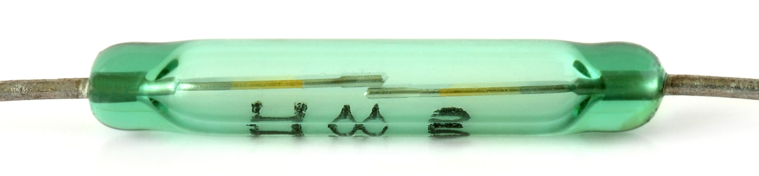
The simplest reed switch consists of two thin, ferromagnetic contacts suspended axially inside a glass tube. The tube is filled with an inert gas, usually nitrogen, and hermetically sealed at the ends. The business ends of the reeds are coated with a non-magnetic material like iridium or tungsten to add strength and durability.
The ends of the reeds overlap slightly with a small gap between them. Whenever a permanent magnet or an active electromagnetic coil comes near the glass body, the magnetic field will cause the reeds to attract and touch, closing the circuit. When the magnet is removed, the flexible reeds spring apart and re-open the circuit.
It Came from Bell Labs
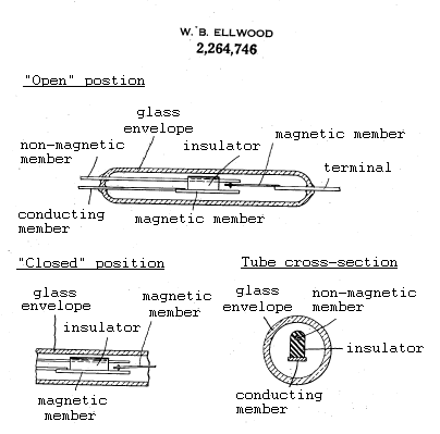
The reed switch was patented in 1941 by Walter B. Ellwood, a Bell Labs engineer. Ellwood was looking to design a cheap and easily replaceable relay unit for switching telecommunications traffic, some kind of simple switch that could withstand heavy use.
The device in Ellwood’s patent drawing is only slightly different from the reed switches out there today. In his design, an actuating reed on one end fluctuates between a magnetic reed and a non-magnetic one on the other, and the two are kept separate by a physical insulator.
Over the next 40 or so years, Bell System and TXE telephone exchanges would use millions of reed relays, first as memory modules and then in speedy crossbar configurations that left the old switches in the dust. Digital telephone exchanges have since put millions of reed relays out of work, but Ellwood’s versatile invention quickly spread to many other industries, like household goods.
House of Reeds
Most of the jobs for reed switches are in sensing or pulse counting, and there is much of both happening in the average household appliance. Any system that requires sensing fluid levels or knowing the positions of parts likely uses a reed switch to do so. Consider the washing machine, which does all of these jobs. When you start a load of laundry, the tub fills with water for the wash cycle. The amount of water it needs is going to be different every time, depending on what you’re washing and in what quantity. Instead of pumping in some set amount of water (and possibly overflowing the tub), there’s a reed switch near the top and a floating magnet that rides the rising tide to meet it and shut off the water.
So you’ve got a load started, but there’s a sock on the stairs that must have fallen out of the basket. You lift the lid and the machine immediately stops filling up with water. Why? Because of another reed switch. This one works by detecting a magnet embedded in the lid. Lifting the lid takes away the magnetic field, so the machine pauses until you throw in that sock and shut the lid. Yet another reed switch is used to measure speed of the drum, taking pulses from a magnet affixed to the tub.
Reed Switches Forever
Reed switches have a pretty solid pedigree of durability and reliability. Even so, they have been replaced by Hall effect sensors in situations that call for a higher degree of precision. Hall effect sensors are faster than reed switches because they’re solid-state devices—no need to wait those few milliseconds for the magnetic field to overcome inertia.
The downside of Hall effect sensors is that they need constant power to operate. That’s because they have to be ready at all times to sense the presence of a magnetic field. They’re also finicky about the position of the magnet and won’t register the Hall effect if the magnet is orientated improperly.
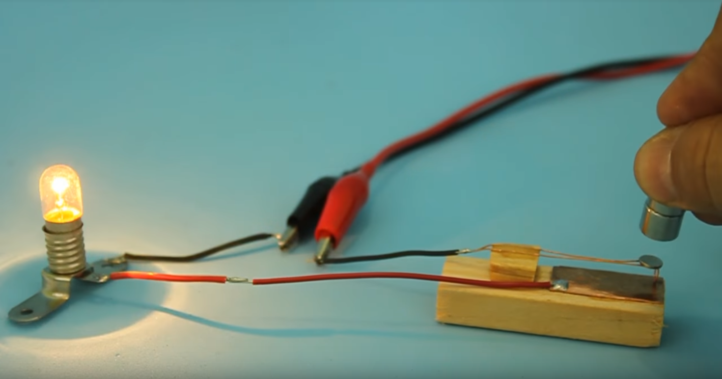
As long as there is a need for simple, non-contact switches, reed switches will be around. Don’t have one around to play with? You can build one in a few minutes with a little bit of copper, some magnet wire, and of course, a magnet.


Seriously! That’s it! I want to do it for long time, but this triggered me! I’m going to steal and print all original art on my wall! They are better and better every time! Kudos to the artist!
Yeah, Hackaday could do pretty well for itself just selling his prints on their store.
Give him a cut of the take.
Of course, that goes without saying. Heck, I’d hope it would be the other way around really.
I agree that this illustration is very nice indeed. It would not look out of place on a 1950’s sci-fi magazine cover.
This one reminds me of the illustration style in the RPG Paranoia.
One of these days Hackaday will use the art to create calendars, and take our money.
And you sir get the one with serial #1
That’s a hella good idea.
Wow this is amazing – I had no idea. Following your blog has opened a whole new world to me. Thank you
I passed over this article yesterday when it was posted, (meh! I know about reed switches.)
But I read it last night, and REALLY enjoyed (and learned from) the comments!
Not to take away from the article or the usefulness of the reed switch, but every washing machine I’ve owned had a simple microswitch activated by a prong on the lid, and I’m pretty sure they mostly use a type of puff switch to detect water level (the water goes up a tube, compressing the air above it into a plastic balloon; when it expands enough, the switch is tripped). Maybe I just buy the wrong kinds of washers :P
Yeah, ours has a reed switch. Shortly after we got it, we wanted to see it in action, so we ran it with a magnet in the right spot to fool it into thinking the lid was closed.
That’s a great trick for laptops too. Often the sensor is in the lid, so you can wave a magnet near the top of someone’s laptop to make it turn the screen off.
On my Asus laptop it’s on the bottom left side, near the power switch. On the HP I used to have a few years back it was also left side on bottom. Location can vary but there is one somewhere on most laptops. The old one that used latch to lock lid down used leaf switch instead of reed switch.
probably should make an internet reed switch database.
My current washer uses a float with magnet in a tube, and, likely, reed switches. My old one used a sealed tube pressure setup. There are other inexpensive options, but given the service (vibration, detergents and corrosives like bleach, suspended dirt, and so on), I would tend toward the no moving parts options.
Yeah, washing machines have used absolute pressure sensors/switches to sense water level for a while. An atmospheric sensor typically has a linear output between 0 and 115kpa. This is sensitive enough to measure the .433psi per foot that water exerts. Figure 2ft of water and .866psi, 1 atmosphere is 100kpa or 14.7psi, that gives you 5.97kpa, or about .259 volts. If the ADC has a 2.5v reference voltage and 255 counts, that would be about 26 or 27 ADC counts at full.
Had to replace a bunch of pressure sensors used as part of a huge commercial horizontal screw-type washing machine you’d find in big commercial laundries. They constantly have water in them, even overnight when not running. The pneumatic lines ran back down to the control cabinet which was below the water level. Imagine my surprise when, having taken the hoses off the original sensors, all this air started rushing out of the lines. Mentioned this to one of the other engineers next to me – he just smiled and waited. Promptly found myself dealing with a handful of airlines now pissing water all over the place. Dooofus. Yay for siphons. Took ages with an aircompressor and blow gun to drive the water back up the lines.
I have the same experiences tearing apart hundreds of appliances.
Float switches haven’t been used since at least the 1960s.
The “puff switch” has largely been replaced with a simple pressure sensor IC (DIP package) mounted on the control PCBA. Bosch is one of the few manufactures, that I know of, who use reed switches, but that’s mostly in their smaller machines, just to save space.
Due to their awesome ability to resist contact bounce and their insanely high rated number of actuation, You’ll even find them in important mechanical switches. The plunger which would normally have just pressed two contacts together is now toggling a magnetic field to actuate a reed switch.
Sometimes more complicated is better.
Well the US is still using top loaders whilst the rest of the world pretty much moved on.
You’d be surprised that in their old technology they are using old technology ?
They use top loaders with vertical shaft. I have a top loader with horizontal shaft which works nearly identical too a typical front loader, except that it has no “bulls eye” but a lid on top and in the sidewall of the drum. This design allows narrower machines.
Hmmm, never seen one…
but, haven’t been looking too hard either!
nonsensical. Please elaborate.
Are you saying I would be surprised, or are you asking if I’m surprised?
How does your USA location effect the question?
What’s the old/new technology exactly? The ability for a front loading door to hold a water tight seal or are you referring to the reed switch, float, puff switch, etc as old tech?
Implication is that top loading is ‘old’? How so? …or is the reed switch ‘old’?
We (as in my parents) had a front loader in 1969 (I turned 7 in the place we rented while my dad remodeled my grandmother home that he purchased).
And I’m on my second front loader myself.
Yeah, a vast majority of the door/lid switches are still contact reed. As for the current draw required of Hall Effect sensors, most of them are in the fraction-of-microamp range and have analog or digital options, are exceptionally tiny, and don’t have breakable glass, which is why phones, tablets, and laptops use them. Additionally, they can sense the difference in polarity. The only real benefit of the reed switch anymore is the simplicity of an on/off connection.
Actually, many hall effect sensors draw quite a large current; the SS39E from Honeywell, for example, draws 6-10mA (this happens to be a type I used in a design recently). I think Hall sensors can be used in low-power application by simply not powering them all the time, but only briefly when a measurement is needed.
The DRV5023 from Texas Instruments (first datasheet result googling “digital hall effect sensor”) draws about 3mA.
If you have references for actual low-current hall effect sensors (especially analog ones), I’d be interested.
how about hall sensor with 20 years on one coin cell from this app note:
http://www.ti.com/lit/pdf/slyy058
They did that by keeping the sensor turned “off” most of the time – it draws 3ma in operation.
Hey it’s the 21st century now. Look at the Allegro product range, e.g. A3212 at 6-10uA, which is about 3 years on a CR2032, and (much) cheaper than reeds.
I’m going to go out on a limb and guess that any Hall Effect device with a CR2032 battery, holder, board and support components will be more expensive than a reed switch. I’m only basing this on the fact that the cheapest junk reed switches I can find have better specs than the Allegro CR2032 and cost less at similar volumes.
Did you actually read the datasheet for the A3212? Page 4, Idd(en), 2.0mA. It turns on for 45uS every 45mS (page 7), giving an average current of 6-10uA (Idd(avg) listed on page 4). 45mS latency is fine for say, turning off a laptop display, but not for many other things.
datasheet: https://www.allegromicro.com/~/media/Files/Datasheets/A3211-12-Datasheet.ashx
Hall switches take a pair amount of current. Decades ago I designed an alarm system and one hall switch took about 10X the power of all of the logic. Reed switches the themselves take no power, but you do waste some power on the on the pull up or pull down going into the logic line they are connected to.
With CMOS the pullup can be a very high value. However that can lead to some odd issues. I recall an expensive Revox open reel recorder randomly popping ping into fast forward or rewind. After much hair pulling it turned out that people chain smoked in the room it lived in, and the switch contacts got coated with deposits from the smoke that conducted enough current would flow to turn the thing on.
Infineon has a 3D hall sensor, that has a wake up capability. It senses the level of each axis and wakes everything up if you leave a certain area. 7 uA typically! And has the advantage of being able to detect manipulation!
I’m sure some washing machines use reed switches, but Maytag top loaders work like you described, without a reed switch in sight.
Also, I suspect a lot of former reed switch applications have switched to its solid state replacement, the hall effect sensor
Came to say the same. I’ve never heard of a washer with a reed switch. Does it work through the metal shell of the washer? All my washing machines had a prong on the lid which pushes a flapper in a little hole. I would assume that the flapper is connected to a plain old mechanical switch although I never took one apart to find out.
I guess that flapper could have a magnet on it which gets pushed up against a reed switch but that seems like a silly design. I would think that the advantages if a reed switch would be the lack of physical opening and the lack of moving parts. Since the little flapper and the hole it lives in are both I’m assuming it’s just a switch.
Oh.. and if you are careful not to slam the door you can even here the click of the switch engaging!
Is it a side ‘which side of the Atlantic do you live on’ sort of thing?
As Winston Churchill said, “We are two nations separated by a common language!”
B^)
I’m a little surprised these things weren’t invented earlier. But sometimes, it takes longer to figure out the simple than the complicated.
And I know Joe’s done “gigantic electrical device” art before, but he’s really outdone himself with this one.
That is ironic, as really its not conceptually different than replacing a solenoid in a relay with a permanent magnet. And that goes back to 1835, So it took over century to simplify it to a reed switch & relay.
I’ve never seen a reed switch in a washing machine. All that I’ve seen used pressure switches to detect the water level. The lid switches I’ve seen were all mechanical snap-action micro-switches.
However, in my Corolla the brake fluid sensor uses a small magnet inside a floating disk. When the brake fluid falls, the magnet will activate a reed switch and the light on the dashboard. (similar setup for low wiper fluid sensor).
In the past, some very reliable keyboards used reed switches on a circuit board activated by magnets in each key plunger. Some mounted the magnets on the circuit board, and the key plunger had a metal shunt to activate the reed switch from the nearby magnet.
http://www.vintagecalculators.com/assets/images/autogen/ToshibaBC0801B_4.jpg
Reeds in mechanical switches are common but that picture appears to show a really bad layout.
The magnet field lines should flow in one lead and out the other. Since I’m sure that thing worked, I can only assume it barely had enough pull to activate the reed and the magnetic shunt was enough to drop the field strength.
The really good ones either send the filed through the reed or around it. That way it’s more robust and requires smaller magnets.
First, you may very well be 100% correct here. :-) That said, when I look at it, I see a very good layout. Each reed is in the center between two identical looking magnets right along the line where a mirror would be if each magnet is each other’s reflection. This symmetrical arrangement allows the entire reed switch to experience zero magnetic field normally whenever no key is pressed if both magnets are opposite in magnetic orientation (along their length). When a key is depressed, one side is effectively much stronger with the help of the magnetic properties of the plunger. (probably just regular ferromagnetic iron) The reed then experiences a magnetic field along its length and closes. I remember seeing a querty keyboard with reed switches on an old piece of calculating equipment my dad brought home for me to play with and tear apart when I was a boy. The quiet ringing sound of the reeds closing whenever you pressed a key was quite pleasant and gave excellent auditory feedback when typing. I’d like to see this tried again with modern components. :-) ????
Reed switches can be damaged by magnetic fields that are too large or applied in the wrong orientation. They’re also susceptible to vibration, and if mistreated, contact welding. If you’re hooking them up to an MCU, you’re also going to have to debounce the signal. They also have a limited cycle life, so you can’t use them for something like indexing a motor.
For these reasons, reed switches are on my do-not-use list. Hall effect sensors and optical interrupters are far more robust solutions.
I was about to mention “mercuty wetted” reed switches, which somewhat adddress both the switch debounce and contact aging. The surface tension of the mercury gives a distinct “make” and “break” action.
Is that what’s in older (central A/C) thermostats? The rotary kind prior to Nest?
Not exactly. The thermostat has a mercury switch, where the mercury flows to the end of a glass capsule and shorts two contacts. A mercury wetted reed switch has a small layer of mercury on the contacts, so any arcing or wear just attacks the mercury, which flows in to repair the damage.
There’s AMR sensors.
https://www.mouser.com/new/murata/murataamr/
As well as MEMS reed.
https://www.electronicproducts.com/Sensors_and_Transducers/Transducers/Alternative_switch_technologies_for_advanced_applications.aspx
I wouldn’t discount them. In fact I would say they are more robust than optical and in many applications more robust than Hall effect.
Luckily damage from magnetic fields is a fifth order function with distance, so if we’re talking a few inches away, you’ll need an MRI machine.
They are very robust when adequately mounted. They tolerate vibration better than most mechanical switches due to their elastic contact arms and the fact a magnetic feild (the thing holding the contacts together) has no momentum. They do have a very hard upper limit and if vibration is near their natural frequency.. that’s an issue, but that kind of vibration would pull damage a PCB anyways. You can get longer arms for better vibration resistance although this affects the magnetic pull-in properties.
They have excellent debounce characteristics due to their low mass, massive relative attractive forces and flexible contact arm. It’s not uncommon to not need a debouce routine in a MCU application.
While most mechanical switches have electrical and mechanical cycle lives measured in tens of thousands or maybe 100k… reeds are measured in millions. Datasheets will rarely note cycle life higher than 1 million because even that number took two years to complete. Practically cycle life is far in excess of single digit millions.
Fast operation, like noting the rotational orientation of a motor as it spins at 1000RPM is an issue because you start getting into magnetic and mechanical issues like the natural oscillating frequency of the contact arms and the fact that the magnetic fields have a hard time changing that fast.
When designing a switch for a high reliability application with massive cycle life and environmental protection or a or a battery powered application that can’t tolerate stand-by power usage, it’s hard to beat a reed switch.
Motorcycles used to rely on reeds to measure the speed.
My enduro used one, and it experienced rough handling, and lots of vibrations, as it it a huge single cylinder (625 ccm).
Only failed, as a rock just sheared off the hole thing from the brake caliper.
In other words you don’t use them even when appropriate as one can misuse them in other applications. Doesn’t seem logical to me.
They are excellent for replacing mechanical switches for low voltage applications being more reliable and having longer life (in general of course).
You seem very down on reed switches, but the crux of ANY design is selection of the right component for the job.
Every comment here that I have so far read has talked about using reeds as sensors, but no-one has mentioned their use as switches (they are called reed switches after all). Some applications need a device to be powered, or not powered, when in the presence of a magnetic field. And for that, none of your other devices can match the efficency of a reed.
Brake fluid sensor in action.
https://standexelectronics.com/wp-content/uploads/Brake-Level-Sensor-Solution_02.gif
Wow, I learn something new here every day. Yet another useful invention out of Bell Labs. I thought I knew pretty much most (or at least a lot) of the great inventions from that once great place but I did not know about the reed switches. Excellent article and, as has already been said, fantastic art work.
It would be nice if there existed a Reed switch that had lots of outputs like a decatron, so it could be used as an insulated rotary encoder without having to have multiple reed switchs.
The driver’s control levers in the British Rail High Speed Train (HST) used an arc of reed switches and a magnet on the end of the lever (opposite end from the knob). Big heavy lever in a big heavy control panel, but the actual switches operated with no force at all as the magnet passed over them. But yes, this used multiple reed switches.
Clever!
Reed switch keyboards were pretty reliable back in the day.
At least 2 major organ makers used them for pedal note contacts. All wiring stays on console, magnets on pedals mate with board full of reeds. Pedals may be removed easily. Dust bunnies live under there as well as mice. No one that I know of has used them for manual keyboards though. They would be dust proof. The common silicone rubber stuff used gets dust underneath (dead notes) and wears out fast under a hard player’s hands.
I had a keyboard from a pocket calculator (or small tabletop calc) which used them, + 2 magnets in each key. I got it as scrap around 30 yrs ago, so it originated from a time when calculators were still really expensive.
I don’t think I’ve seen reed switches on laptops before. Only micro switches then hall sensors
I remeber taking apart an all-in-one computer from the 70/80s, it had a lot of reed relays inside; horizontal coils with a glass reed ampoule floating down the center, not all encompassed as one component. I broke them trying to remove them :(
Quote [Kristina Panos]: “Over the next 40 or so years, Bell System and TXE telephone exchanges would use millions of reed relays, first as memory modules and then in speedy crossbar configurations that left the old switches in the dust.”
The Bell System mention was “Cross-point Switching” rather than “Cross Bar Switching”.
I very slip of the tongue to make as they have far more in common than just the similarity of name.
Both were a way of having primitive memory store and maintain connected signal paths.
I don’t know much about “Cross-point Switching” except that it used residual magnetism in ferric metals (Remanence) to maintain the signal connection path.
However I do know a little about “Cross Bar Switching” and I expect that would be very similar in principle.
Cross Bar Switching incorporated three techniques.
1) The signal matrix – like a relay matrix where any input can be connected to any output. This is the most commonly known element.
2) The control matrix – like a led array where any control point can be accessed as a matrix element instead of single control points.
3) The memory to hold the signal path so that subsequent signal routing does not interfere with established signal paths.
The signal matrix was made up of modified relays in a matrix layout.
The control matrix was made up of a columns of relays (driven simultaneously) and the crossbars.
Once a signal path was established it was held by control of the connected circuits.
The cross bar and how it worked with the relays is the interesting feature.
There were 5 crossbars and 100 or so relays. None of the relays could independently activate it’s contacts as the mechanical path to do so was incomplete.
The crossbars had short lengths of spring steel wire that would complete the mechanical path for the relay to operate it’s contacts only when the crossbar was deflected in that direction. Crossbars could be deflected up or down to accommodate two rows of relays each.
When the crossbar returned to the neutral position the relay would hold one of these spring steel wires until the relay released under the control of external circuitry at a later stage. This is the so called “memory”.
The same crossbar could then be used to engage other signal paths in the same way as the existing paths remained due to the flexible spring steel wire.
The vertical columns of relays were operated together. This didn’t bother existing circuits as the relay was already operated and had clasped the spring steel.
Only the relay in the column that had the spring steel caused from the deflected crossbar would operate the contacts and latch and the others would drop out again unless they had an established signal path.
So the advantage of the crossbar switch was the matrix control signals.
In a 10 by 10 matrix of relays (not crossbar) you have one wire to operate each relay which is 100 wires.
With the addition of an extra 10 crossbar deflectors in the crossbar configuration you only have 20 wires.
engine driven welders use them to increase the engine speed when an arc is struck. Lincoln engine driven welders have two reed switches directly in the welding circuit.
In my washing machine here was a different application for a reed switch: sensing the position of the drum when it stops. So opening in the drum (rotating around a horizontal axis) lines up with the opening on top of the machine so you do not have to manually rotate the drum until you can access the inner lid of the drum.
The outer lid (of the machine) is not sensed but locked, by a thermal actuator which takes annoying 3 minutes to release the door locking mechanism. The water level is not checked by a float but by a tube with a pressure sensor (diaphragm switch).
The reed relay is widely used in test equipment and test rigs. It’s a very good switch, fully isolated, in a small package. Digital scopes use them in the analog front end for gain/attenuation switching. Some digital voltmeters have a similar arrangement. You can sometimes hear them clicking when you change the range switch settings.
Fun additional fact: The body of the electrode wires in reed switches is made from Alloy 52, a nickel/iron alloy with a thermal expansion coefficient equal to that of soda-lime glass, which is what the envelope is made from. They make an excellent cheap source of electrodes for sealing into glassware for vacuum tubes ;-)
This is the kind of information I come to HaD for.
The comment section often has a wonderful little hidden gem like this buried under a mountain of noise with an apex of /facepalm.
On a separate, but related note(?)…
How do those washing machine water level switches that use air pressure operate?
Specifically, what does the “reset” position operate?
s/what does/how does
My favorite use of the reed switch is as the commutator in lasersaber’s ez spin motor (which can spin for quite a while on a standard electrolytic cap thanks to sapphire bearings and other high efficiency tricks) https://hackaday.com/2016/01/01/ez-spin-motor-spins-forever/
Came for the artwork, read through all the great comments about something electronic something.
Still can’t figure out what any of this has to do with Lou Reed. (RIP).
Lou Rawls (RIP)
Reed switches are used all the time in outdoor anemometer ( wind speed ) detectors. If you have one in your hand you can hear the reed click as the “whirly-cups” spin about. It is normal for the cheap $100 Chinese models. I don’t remember checking for that on the better Davis brand unit I’m using now. :-) ????
Reed switches are also used on electric bikes, namely the crank (pedal) sensors, speed sensor and brakes.
As this is a safety critical application and has legal implications if it breaks nothing else will work whereas the pushbutton or Hall sensor used on the twist throttles is sometimes just a $0.99 part.
If the manufacturers were sensible they’d use two switches in a push-pull arrangement with resistors so if any one failed the bike would run but speed limit to 8mph for safety reasons (see pedal sensor)
A new type of inductor, laminated graphene doped with bromine, and using kinetic, instead of magnetic.
http://www.spacedaily.com/reports/Reinventing_the_inductor_999.html
“The revolutionary inductor, which works in the 10-50 GHz range, offers one-and-a-half times the inductance density of a traditional inductor, leading to a one-third reduction in area while also providing extremely high efficiency. Previously, high inductance and reduced size had been an elusive combination.
“There is plenty of room to increase the inductance density further by increasing the efficiency of the intercalation process, which we are now exploring,” said co-author Jiang.
“We essentially engineered a new nanomaterial to bring forward the previously ‘hidden physics’ of kinetic inductance at room temperature and in a range of operating frequencies targeted for next-generation wireless communications”