There is something strangely amusing about the idea of a sprinkler system relying on a cloud. But it was this limitation in some commercial offerings that led [Zack Lalanne] to create his own controller when it was time to upgrade his aging irrigator.
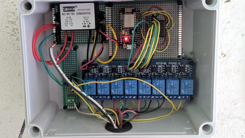
It’s a straightforward enough device, he’s taken an ESP8266 on the ubiquitous NodeMCU board, and added a shift register for some output line expansion to drive a set of relays. The interest here lies with the software, in which he’s used the ESPHome firmware and added his own custom part for the shift register. This change alone should be useful for many other experimenters with the ‘8266 and ESPHome combination.
The ESP8266 end of the device ties in with his instance of the Home Assistant home automation hub software. On this he’s been able to tie in all his various sprinkler outputs he added, and apply whatever automation scripts he chooses. The result is a freshly watered lawn, with not a cloud in the sky (or backend).
The value of this project lies only partly in its use for sprinkler owners, for us it also lies in the clear write-up showing the way for others with similar home automation tasks. It’s not the only way to make an ESP sprinkler controller, you should also see this one from 2017.


You can also use a MCP23017 instead of a shift register and directly address the outputs. You can add up to 128 I/O, 16 per chip. Only two I/O is needed to communicate to all the expander chips using I2C. Same I/O gets real time clock data from a DS3231 chip. All data is displayed on a web page hosted on the controller. Details and other applications are here:
https://sites.google.com/site/nodemcu12e/
You have to load the Adafruit library then just put “mcp.” in front of I/O commands.
New command examples to use MCP23017:
#include “Adafruit_MCP23017.h” //MCP23017 I/O expander see library example.
Adafruit_MCP23017 mcp; // MCP23017 I/O expander gives 16 more digital I/O to board using I2C
mcp.pinMode(8, OUTPUT); // Initialize mcp 5 pin as an output on MCP23017
mcp.digitalWrite(8, HIGH); // Since relays are active LOW write High to outputs initially.
Looks like the schematic from https://opensprinkler.com/ I’ve used their Pi version for years.