If you’ve ever cast your eyes towards experimenting with microwave frequencies it’s likely that one of your first ports of call was a cheaply-available Doppler radar module. These devices usually operate in the 10 GHz band, and the older ones used a pair of die-cast waveguide cavities while the newer ones use a dielectric resonator and oscillator on a PCB. If you have made your own then you are part of a very select group indeed, as is [Reed Foster] and his two friends who made a Doppler radar module their final project for MIT’s 6.013 Applications of Electromagnetics course.
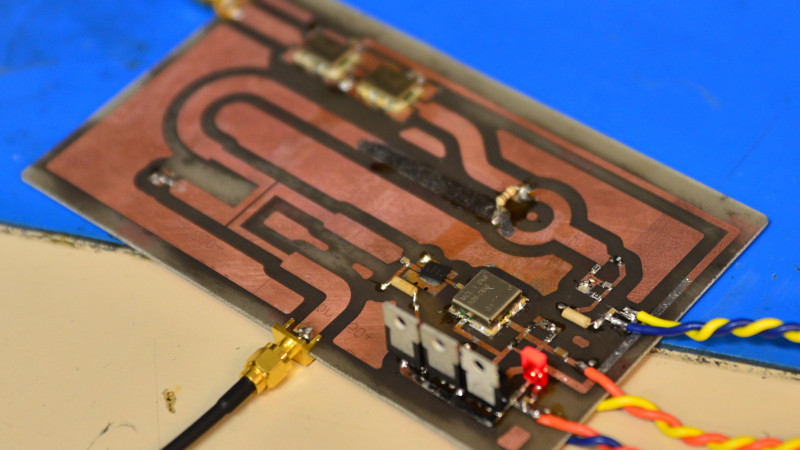
Their module runs at 2.4 GHz and makes extensive use of the notoriously dark art of PCB striplines, and their write-up offers a fascinating glimpse into the world of this type of design. We see their coupler and mixer prototypes before they combined all parts of the system into a single PCB, and we follow their minor disasters as their original aim of a frequency modulated CW radar is downgraded to a Doppler design. If you’ve never worked with this type of circuitry before than it makes for an interesting read.
We’ve shown you a variety of commercial Doppler modules over the years, of which this teardown is a representative example.


Ham radio enthusiasts have been building similar devices for many decades. Back in the 1950s many used surplus klystron tubes built in to a coffee can with a suspended mixer diode in it. The idea morphed a bit in the late 1970s/early 1980s in to what came to be known as a Gunnplexer. They used Gunn diodes to oscillate and there was a varactor in the tuned cavity to push the frequency around electronically. I still have a pair.
I also have a pair of Chinese DRO doppler radar units. Haven’t played with them yet because I’ve been doing too much business travel these days.
If one is interested in ranging, you can sweep the CW radar and then measure the return signal beat frequencies. Of course, you’ll need to calibrate the sweep rate and ranging.
And finally, you can build a very cheap retro-reflector by building a cheap half wave dipole with a PIN diode in the middle. Bias the PIN diode on and off at some IF frequency and this will modulate the return signal. You can put intelligence on that retro-reflector too. So for example, you could modulate the PIN diode with a digital signal and use this a low power method to convey data back to a radar system.
There are lots of fun things you can do with these devices.
NFC / FFC (Far field communication?) for your plane, nice! But is it really retro-reflector? I mean RR are directional, I don’t think dipole would be directional. Could this be used as active radar signal suppression?
This is a microstrip design, not a stripline design. Two different but related transmission lines.
I cobbled up one of those for the 1972(?) Commander’s Day Open House at Griffiss AFB. I scrounged an X band klystron, circulator, diode detector and small parabolic (easy to find at a radar laboratory) and hooked the output up to my guitar amplifier. Put up some posters on radar detection and waited for passersby, Or just rode my bike around (this was in a large hangar).
The next Open House somebody made a baseball speed detector with the same idea, with an audio frequency counter.
Commander’s day got boring by the 80s. Just planes by the time I was old enough to enjoy it. I grew up north of Rome in a nonmilitary family but dad is a mechanical engineer and definitely would have pointed radar experiments to us.