Doppler Speed Sensor Puts FFT And AGC To Work

Some people hate to revisit projects that are done and dusted. We get that; it’s a little like reading a book you’ve already read when there are so many others to choose from. But rereading a book sometimes reveals subtle nuances you missed the first time around, and revisiting projects can be much the same, as with this new and improved Doppler radar speed sensor.

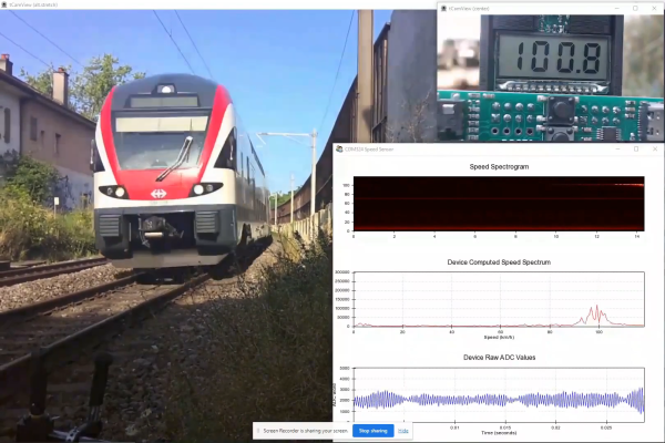
We seem to have been remiss in writing up [Limpkin]’s last go-around with the CDM324 microwave module, a 24-GHz transceiver that you can pick up on the cheap from the usual sources, but we’ve featured this handy little module in plenty of other projects. [Limpkin]’s current project uses the same module to create a Doppler speed sensor, but with a little more sophistication all around. Whereas the original used a simple comparator to output a square wave that’s proportional to the Doppler shift and displayed the speed on a simple terminal session, version two takes a different tack.

First, [Limpkin] opted to implement the whole sensor in hardware. The front end is quite different — an op-amp with 84 dB of gain followed by an automatic gain control (AGC) stage built from a MAX9814 microphone preamp. Extraction of the speed from the module output is left to an STM32F301 running an FFT algorithm on the signal coming out of the analog circuit, which essentially picks out the biggest peak in the spectrum and calculates the Doppler shift from that, displaying the results on an LCD display.

Of course, as a [Limpkin] project, there’s a lot more to it than just that. The write-up is very detailed, going down a few enjoyable rabbit holes like characterizing the amplification chain and diving into the details of Johnson-Nyquist noise to chase down stray oscillations. There’s some great stuff here, and it’s well worth a deep read; there’s also the video below that lets you see (and hear) what’s going on.

Continue reading “Doppler Speed Sensor Puts FFT And AGC To Work”

Take A Deep Dive Into A Commodity Automotive Radar Chip

When the automobile industry really began to take off in the 1930s, radar was barely in its infancy, and there was no reason to think something that complicated would ever make its way into the typical car. Yet here we stand less than 100 years later, and radar has been perfected and streamlined so much that an entire radar set can be built on a single chip, and commodity radar modules can be sprinkled all around the average vehicle.

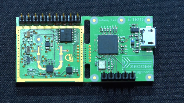
Looking inside these modules is always fascinating, especially when your tour guide is [Shahriar Shahramian] of The Signal Path, as it is for this deep dive into an Infineon 24-GHz automotive radar module. The interesting bit here is the BGT24LTR11 Doppler radar ASIC that Infineon uses in the module, because, well, there’s really not much else on the board. The degree of integration is astonishing here, and [Shahriar]’s walk-through of the datasheet is excellent, as always.

Things get interesting once he gets the module under the microscope and into the X-ray machine, but really interesting once the RF ASIC is uncapped, at the 15:18 mark. The die shots of the silicon germanium chip are impressively clear, and the analysis of all the main circuit blocks — voltage-controlled oscillator, power amps, mixer,  LNAs — is clear and understandable. For our money, though, the best part is the look at the VCO circuit, which appears to use a bank of fuses to tune the tank inductor and keep the radar within a tight 250-Mz bandwidth, for regulatory reasons. We’d love to know more about the process used in the factory to do that bit.

This isn’t [Shahriar]’s first foray into automotive radar, of course — he looked at a 77-GHz FMCW car radar a while back. That one was bizarrely complicated, though, so there’s something more approachable about a commodity product like this.

Continue reading “Take A Deep Dive Into A Commodity Automotive Radar Chip”

How On-Frequency Are Those Cheap Radar Modules?

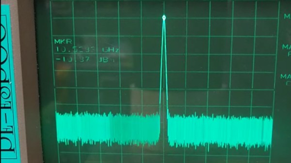
If you’re partial to browsing AliExpress, Banggood, or eBay for unusual hardware, you may have seen the HB100 Doppler Radar modules. These are a PCB with a metal can on board, and their reverse side has a patch antenna array. They work on a frequency of 10.525 GHz, and [OH2FTG] has characterized a few of them to see how close they lie to that figure.

These devices have a superficially very simple circuit that makes extensive use of PCB layout for creating microwave inductors, capacitors, and tuned circuits. There’s a FET oscillator and a diode mixer, and a dielectric resonator coupling the output and input inductors of the FET. This component provides the frequency stability, but its exact frequency depends on what lies within its electric field. Thus the screening can does more than screening, and has a significant effect on the frequency and stability of the oscillator.

The higher quality HB100s have a small tuning screw in the top of the can which in turn adjusts the frequency. This should be tweaked in the factory onto the correct point, but is frequently absent in the cheaper examples. In this case he has a pile of modules, and while surprisingly some are pretty close there are outliers that lie a significant distance away.

If you use an HB100 then the chances are nobody will ever bother you if it’s off-frequency, as its power output is tiny. But it’s worth knowing about their inner workings and also how to adjust them should you ever need to. Meanwhile if you’re interested in Doppler radar, here’s how to design one for a lower frequency.

Continue reading “How On-Frequency Are Those Cheap Radar Modules?”

Keep An Eye On The Neighborhood With This Passive Radar

If your neighborhood is anything like ours, walking across the street is like taking your life in your own hands. Drivers are increasingly unconcerned by such trivialities as speed limits or staying under control, and anything goes when they need to connect Point A to Point B in the least amount of time possible. Monitoring traffic with this passive radar will not do a thing to slow drivers down, but it’s a pretty cool hack that will at least yield some insights into traffic patterns.

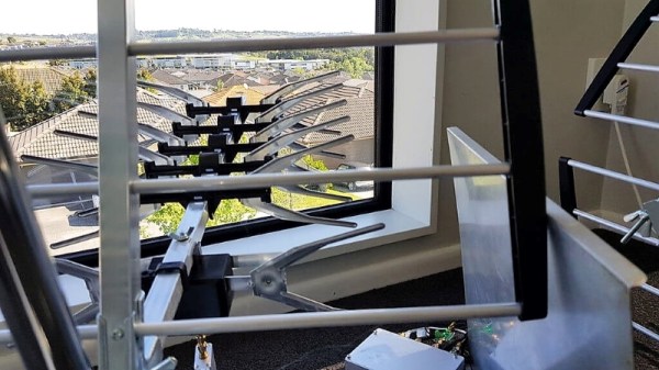
The principle behind active radar – the kind police use to catch speeders in every neighborhood but yours – is simple: send a microwave signal towards a moving object, measure the frequency shift in the reflected signal, and do a little math to calculate the relative velocity. A passive radar like the one described in the RTL-SDR.com article linked above is quite different. Rather than painting a target with an RF signal, it relies on signals from other transmitters, such as terrestrial TV or radio outlets in the area. Two different receivers are used, both with directional antennas. One points to the area to be monitored, while the other points directly to the transmitter. By comparing signals reflected off moving objects received by the former against the reference signal from the latter, information about the distance and velocity of objects in the target area can be obtained.

The RTL-SDR test used a pair of cheap Yagi antennas for a nearby DVB-T channel to feed their KerberosSDR four-channel coherent SDR, a device we last looked at when it was still in beta. Essentially four SDR dongles on a common board, it’s available now for $149. Using it to build a passive radar might not save the neighborhood, but it could be a lot of fun to try.

A Doppler Radar Module From First Principles

If you’ve ever cast your eyes towards experimenting with microwave frequencies it’s likely that one of your first ports of call was a cheaply-available Doppler radar module. These devices usually operate in the 10 GHz band, and the older ones used a pair of die-cast waveguide cavities while the newer ones use a dielectric resonator and oscillator on a PCB. If you have made your own then you are part of a very select group indeed, as is [Reed Foster] and his two friends who made a Doppler radar module their final project for MIT’s 6.013 Applications of Electromagnetics course.

Their module runs at 2.4 GHz and makes extensive use of the notoriously dark art of PCB striplines, and their write-up offers a fascinating glimpse into the world of this type of design. We see their coupler and mixer prototypes before they combined all parts of the system into a single PCB, and we follow their minor disasters as their original aim of a frequency modulated CW radar is downgraded to a Doppler design. If you’ve never worked with this type of circuitry before than it makes for an interesting read.

We’ve shown you a variety of commercial Doppler modules over the years, of which this teardown is a representative example.

Radio Gets Ridiculous

There were plenty of great talks at this year’s Supercon, but we really liked the title of Dominic Spill’s talk: Ridiculous Radios. Let’s face it, it is one thing to make a radio or a computer or a drone the way you are supposed to. It is another thing altogether to make one out of things you shouldn’t be using. That’s [Dominic’s] approach. In a quick 30 minutes, he shows you two receivers and two transmitters. What makes them ridiculous? Consider one of the receivers. It is a software defined radio (SDR). How many bits should an SDR have? How about one bit? Ridiculous? Then you are getting the idea.

Dominic is pretty adept at taking a normal microcontroller and bending it to do strange RF things and the results are really entertaining. The breadboard SDR, for example, is a microcontroller with three components: an antenna, a diode, and a resistor. That’s it. If you missed the talk at Supercon, you can see the newly published video below, along with more highlights from Dominic’s talk.

Continue reading “Radio Gets Ridiculous”

SDR Is At The Heart Of This Soup-Can Doppler Radar Set

Want to explore the world of radar but feel daunted by the mysteries of radio frequency electronics? Be daunted no more and abstract the RF complexities away with this tutorial on software-defined radar by [Luigi Cruz].

Taking inspiration from our own [Gregory L. Charvat], whose many radar projects have graced our pages before, this plunge into radar is spare on the budgetary side but rich in learning opportunities. The front end of the radar set is almost entirely contained in a LimeSDR Mini, a software-defined radio that can both transmit and receive. The only additional components are a pair of soup can antennas and a cheap LNA for the receive side. The rest of the system runs on GNU Radio Companion running on a Raspberry Pi; the whole thing is powered by a USB battery pack and lives in a plastic tote. [Luigi] has the radar set up for the 2.4-GHz ISM band, and the video below shows it being calibrated with vehicles passing by at known speeds.

True, the LimeSDR isn’t exactly cheap, but it does a lot for the price and lowers a major barrier to getting into the radar field. And [Luigi] did a great job of documenting his work and making his code available, which will help too. Continue reading “SDR Is At The Heart Of This Soup-Can Doppler Radar Set”