You may have noticed, we’re fans of the Raspberry Pi here at Hackaday. Hardly a day goes by that we don’t feature a hack that uses a Pi somewhere in the build. As useful as the Pis are, they aren’t entirely without fault. We’ve talked about the problems with the PoE hat, and multiple articles about keeping SD cards alive. But a new failure mode has popped that is sometimes, but not always, caused by shorting the two power rails on the board.
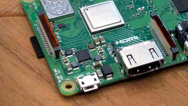
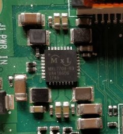
The Pi 3 B+ has a new PMIC (Power Management Integrated Circuit) made by MaxLinear. This chip, the MxL7704, is a big part of how the Raspberry Pi foundation managed to make the upgrades to the Pi 3 without raising the price over $35.
A quick look at the Raspberry Pi forum shows that some users have been experiencing a specific problem with their new Raspberry Pi 3 B+ units, where the power LED will illuminate but the unit will not boot. The giveaway is zero voltage on the 3v3 pin. It’s a common enough problem that it’s even mentioned in the official boot problems thread.
Make sure the probe you are measuring with does not slip, and simultaneously touches any of the other GPIO pins, as that might instantly destroy your PI, especially shorting the 3V3 pin to the 5V pin will prove to be fatal.
Word From the Top: We’re Working On It
After experiencing this failure mode first-hand I decided to investigate. I reached out to the Raspberry Pi Foundation, and got a response directly from Eben Upton about the issue. He confirmed that there is a known issue: Shorting the 5V and 3V3 pins of the Raspberry Pi 3 B+ will permanently damage the PMIC. Of course shorting out power rails is a user error, but since it’s a mistake encountered by quite a few of us, they’re working on a way to fix the issue.
The interesting thing is that Eben acknowledged that a few people have experienced this failure without shorting the power pins, but it’s proven extremely difficult to troubleshoot. They are in search of someone who can reliably replicate the 3V3 failure without simply shorting the power pins. Eben even said “I would fly an engineer anywhere in the world to meet someone who can do this.” It’s not hard to see why this failure mode is so hard to track down — you can only perform it once and then the damage is done. Here’s their contact form if you happen to have info that can help.
This PMIC Fault is Not User Serviceable
The official solution to a 3V3 line failure is to contact the distributor and request a replacement Pi. The MxL7704 is officially considered not a user serviceable part. That’s obviously not enough to stop us, so I thought I’d try swapping out the bad chip for a replacement.
The MxL7704 is available through Mouser, so I ordered a couple and tried my hand at replacing the chip. Even with a hot air rework station, soldering the 0.5 mm pitch chip was too fine for me to master for this project. I discussed this with Eben and he mentioned that the chip from Mouser isn’t actually a drop-in replacement for the one on the Raspberry Pi, and suggested replacing the chip with one from a working Pi 3a+. It’s not clear to me if there are actual silicon changes, or if the differences are all in the i2c programming of the PMIC.
For all you Pi 3+ owners out there, be careful you don’t accidentally short pins on the new Raspberry Pis, as it will almost certainly brick the device. If you manage to recover your Pi by swapping out the PMIC, be sure to let us know!


Doctor, it hurts when I do this!
Then don’t do this!
I hope minde don’t do that when I buy it
– but i have to.
– why?
– because it brings relief.
– how?
– when i stop.
This can go on and on…
I, too, experienced this problem with an RPI3 recently. I DEFINITELY shorted the 3V pins together; I foolishly was trying to wire in some simple LEDs and DID NOT TURN OFF THE POWER FIRST!!!! (bad move, always).
Another $35 & a 1.5 day wait for shipping and I had my new PI all ready to go.
Note: although the PI was dead, the SD card was undamaged so I didn’t lose any data or programming.
So many chips nowadays are so robust to bad voltages, it’s actually become somewhat startling when a short causes immediate, permanent damage. I’m particularly used to industrial hardware, where they explicitly expect a monkey without eyes to install the stuff – by necessity, it’s capable of withstanding any wiring configuration you care to attach to it for days or even weeks at rated voltage (24V), and most of it will survive the same thing at 120 for a while.
Still, I’m curious what the failure mode here is. Is the 3V3 rail getting pulled to 5 and cooking the PMIC? Are the 3V3 clamp diodes insufficient? Does the pi even have rail clamp diodes?
It could be the 5V going into the synchronous rectifier i.e. a MOSFET that shunt to Gnd when the Top MOSFET turns off. This improves efficiency over a Schottky because of lower forward voltage drop.
If the 5v is shorted to 3.3V, the PWM is reduce to 0% because the output voltage is higher than preset. So sync FET is full at 100%. The 5v also bypasses the Top MOSFET and goes into the sync FET that is now shorted to Gnd at 100% duty cycle = smoke.
Your don’t want 5v on 3.3v device. But your can do the other way
Exactly as [tekkieneet] said:
OVP (Output Over Voltage Protection)
In the event that an output is inadvertently connected to a source higher than the target voltage of the buck regulator, the buck regulator will do all it can to clamp that voltage. It is the natural response of the control loop to turn on the low side MOSFET to try and clamp the output voltage. The buck regulator will do so in an effort to protect the lower voltage, higher value circuitry to the point of destruction.
(From the datasheet)
so replacing the 3,3V regulator with a ~3,7 to 4V one and a diode would prevent external power from triggering the OVP?
Well hindsight is 20/20….
That’s fine, but I would have expected the high current to cause the 5V supply to note a fault and shut down. Though I suppose in this case the “5V supply” might just be the bare USB voltage – in which case the failure makes sense.
Ha, yeah, I once had to help make a piece of industrial hardware. Every pin that can interact with the outside world needs to be able to tolerate anything that could go to any other pin, and then some.
“But that arrangement of pins can’t happen, because the connector shape would prevent it from fitting!” you say? Doesn’t matter, because there’s always the risk that some factory worker with poor spatial awareness and a big hammer will MAKE it fit.
Like the un-named Russian who forcibly installed a sensor upside down on one of their (fortunately unmanned) rockets. Idiots gotta idiot. Or saboteurs gotta sabotage.
I can believe it was an honest fuckup. I’ve seen too many “electricians” wire things in ways that make absolutely no sense, and too many “installers” who would rather break out the side grinder than report that they’ve got the wrong part (or alternatively, acknowledge that they’re using the part completely wrong). To any engineer and most hackers it seems like complete madness, but that’s factory life for you. “Keep poking the wires into things until the green light comes on” is a tried and true strategy.
Green means stop.
A friend of mine tried that with a clone army bot at university.. Seemed fool proof and target bot enjoyed it.. but the clone bot down the hall had a crowding socket and all the sudden its rumored to kanger roo bot studies… Er bot court that even though she bot bought him a handle.. She might have smelled it. Clone bot down the hall was not rocking ecc and pretty concerned with wires u poked.. Sooo… Now we have one more lib arts grad and the ee was male so no one but the economy will feel the loss of this half breed wanna be ee.
David’s obviously familiar with this tale lol
I need to get out more
Murphy’s Law was the result of a technician installing three accelerometers the same wrong way. There were 3 right ways and only one wrong way, and he did the wrong way three times. They were on Col. Stapp’s rocket sled, which he rode to determine gee tolerances for fighter pilots. After the very first run, Stapp popped the 5-point restraint and staggered over to the instrumentation shed, where Murphy was looking at totally blank traces on the strip chart recorders for the X, Y, and Z accelerometers.
Murphy then went out and looked ATM the accelerometers, and said in disgust, “If it can be done wrong, it will be!” And that was the original formulation of Murphy’s Law.
There also is always a possibility of a fault in a wiring harness and you get e.g. the 24V of a vehicle battery to a sensor or communication input. In such a case it is always helpful if these are protected.
Lets see what people have to say, but if the part from Mouser is the same part #, then why would it not be a replacement ?
And if the part is somehow rom-programmable , is there information about it on the pcb/gerber/source/documentation files ? Making a temporary gig to program it before replacing would not be too hard if it is i2c.
from https://www.mouser.com/datasheet/2/146/MXL7704-1315918.pdf :
“Two pre-programmed standard products are available.
The MxL7704-X has been optimized for powering the Xilinx® Zynq® Ultrascale+™ ZU2 and ZU3 MPSoCs.
-snip-
The MxL7704-A is designed to power a wide range of ARM® Cortex®- based processors (A7, A9, and A53) which use a more conventional sequencing scheme…”
That mentions OTP config in the ordering info and Table 10 shows default values. Seems like it’s made-to-order and one-time-programmed differently from either of those, and we can’t buy blanks.
OTOH those are just defaults, what happens if you put e.g. an ATtiny on there and have it set everything to what you read out of the registers in a good Pi? I bet one could put a pulldown resistor on SEQ EN, then have the ATtiny write your copy, and only then allow the MxL7704 to power up its outputs. (yeah “someone” could, my Pi 3 B+ still works)
They’ve said explicitly that there is more customisation in there than what is exposed via the registers.
Ah, I didn’t get that. Thanks
Looks like it seems trivial to figure out the proper settings for the chip to make it a drop in.
From the data sheet the only settings that are set by 400kHz i2C is:
• power up and down sequencing
• assign PGOOD outputs to the PGOOD pins
• enable outputs and select switching frequency
They’ve also altered the power-on default voltage for some of the outputs to suit the Broadcom SoC + RAM. Replacing it with the generic part works but the SoC + RAM voltages are wrong.
I’m gonna say it: using an OTP part, that’s proprietary and you can’t hack replace it yourself… feels like the RPi foundation is getting further from its initial goals every day.
Good heavens- does that matter that much? The Pi’s are still running a closed-source GPU+CPU. I’m not quite sure that a closed-source almost-jellybean is a good thing to pick a fight over.
You’re not wrong, but it’s a step in the wrong direction and honestly it’s frustrating.
Further from its Initial goals? Nothing has changed. The Raspberry Pi Foundation has never been about open source or open hardware. Their goal has always been teaching computer science to school kids. I don’t know why people automatically assume they’re a leading example of open source and open hardware when that has never been their goal.
If their original goal is teaching computer science to school kids, and they make a device that can be bricked very easily by an untrained slip of a hand…. aren’t they moving further from their initial goals?
Perhaps, though the Pi has always had this problem to some extent. In a presentation I saw on how to use Pis in education from someone with experience of doing so, he even specifically warned not to use the onboard GPIOs in lessons. If you want to run a lesson that does require IO, apparently you should use Arduinos plugged into the Pis for all the interfacing. (To be honest, I doubt any of the modern Linux-based boards would be robust enough for this use. The chips they use are intended for tablets, not breadboards.)
Was the rPi foundation ever particularly about open hardware?
They are certainly about making programming and tinkering widely accessible and cheap; with some emphasis on learning like kids did in the days of classic computers; so they don’t just slap a lockdown environment with some pedagogical language on their gear and call it a day; but from the very beginning they were using somewhat inaccessible hardware(BCM chips that you normally didn’t even see outside of high volume products) to deliver on the ‘cheap’ part; and while their board support is markedly above average for cheap ARM boards(and slightly astonishing to anyone whose memories of Broadcom involve dissecting their Windows drivers just to get firmware to try to make their WiFi parts work under Linux); that has been more in the service of expanding the area you can tinker with rather than a commitment to open hardware in itself.
All that said, unless there’s something about PMIC configuration I don’t know; I’m not sure why it’s a secret worth keeping; and if you want people to help you debug your PMIC problem making it at least possible to swap the part if it dies seems like it would be a good move.
The part numbers aren’t the same. The part on the 3B+ is a MxL7704-R3 which is a specially configured version for the 3B+ that has altered to suit the Broadcom SoC. People have replaced the MxL7704-R3 with the generic part and it does turn on but the SoC voltage rails are wrong.
Well, there are parts of the R3 marking in aliexpress. If they are genuine would be another discussion.
But as the parts are i2c programmable, someone could replace them with the generic variant, and interpose something to reprogram it via i2c before enabling the voltage rails.
So… is anyone going to tell us about the website getting hacked?
Was anything leaked that you know of? Right now unless I’m missing something you guys just removed the posts and swept this under the rug like nothing happened.
https://hackaday.com/2019/06/11/the-day-hackadays-theme-was-broken/
They literally posted about this yesterday. It’s still on the front page for crying out loud
https://hackaday.com/2019/06/11/the-day-hackadays-theme-was-broken/
It’s not on the front page of NYT, WSJ, People, ET, Vogue, Elle, SI. I call cover up!!!
(c:
“Did you hear about this thing? Mainstream media is refusing to report on it and is trying to cover it up!”
“Where’d you hear about it?”
“Mainstream media.”
Back in the early ’80s when I was an early teenager I built a z80-based tuneful doorbell from a kit. After it did nothing I realized I’d put the z80 in its socket the wrong way round. So of course I just turned it around and powered up again…and it worked! :-D
I’ve done this and had chips get hot to touch, still worked afterwards too …
One of my first Arduino projects was using an Uno to control the red, green, and blue electron guns in a small CRT TV. It was working fine and suddenly stopped. A few minutes of checking all the wiring showed the chassis ground strap had fallen and landed across the atmega328 on the Uno. I gently moved the strap and felt the chip to see if it was warm. It burned a blister on my thumb.
Once it cooled down, it worked just fine.
Some chips are just indestructible.
Taught an AVR class where someone reversed power rails on an ATmega88. Got hot enough that we had to wait to pull it out of the breadboard. After which, it was just fine.
But here, as tekkineet pointed out above, the analogy is shootthrough on an H-bridge. I don’t have enough fingers to count all the H-bridges I’ve killed in my life. (Only a couple from shootthrough, though.)
I believe it might’ve been your advice, Elliot, that got me started using uC GPIO pins as H-bridges for sufficiently small motors. Haven’t burned up nearly enough of those yet; I gotta build more motorized projects!
My only backward chip I can remember, not to say that it never happened beside that, was me replacing the 386 or possibly 486 CPU in my boss’ computer with a boosted version from another company, I do not remember the details except that it was more likely to be a 386 than 486. The socket or cpu replacement weren’t keyed and I ended up putting it in backward because I did not take note (we did not all have an instant camera in our pocket back then) and relied on my memory. It fried both cpu and motherboard.
I did not get in trouble because when you work in electronic shit happens and my boss ended up with what he wanted all along, a more powerful computer to replace the dead one.
With that said I’ve since been a lot more careful and can’t remember installing something expensive backward with bad results or not. A good friend before unplugging unkeyed connectors is a marker.
This last sentence. Also when you’re dealing with identical connectors with different functionality.
I once designed a PCB that provided VSS and VDD to a W65C22 VIA and got the rails the wrong way around. That chip worked once I reworked the board as well.
That luck depends mostly on the capability of the PSU.
Similar with a stereo (where somebody decided to build it with center-negative DC socket):
One time with reversed polarity on a (probably not fully charged) 12V/7Ah SLA battery only a Z-diode was converted to a “47 ohm resistor”. After replacement everything was OK.
Several years later the source was a pair of car batteries @14,4V (full sun on the PV panel). Probably every IC blown. I did not even try to get replacement parts for a 30yr old device.
Is this a warning from the future that a hack is incoming? :Looks around suspiciously:
Last week at my Tech Jam – “The computer screen has gone blank”, “That’s because you’ve shorted out the power supply on the breadboard”. Thankfully, it was a 3B, not 3B+ so it rebooted no problem. However, I’m not going to rush to buy any 3B+ for Tech Jams in the future.
One of the unwritten rules in assigning pin out is to put GND pin next to power pins. It helps to minimize the loop area of return path AND if use correctly to separate different power rails for silly human errors like this.
e.g. floppy/PATA power pins: +5v Gnd Gnd +12V , SATA: +3.3V Gnd 5V Gnd 12V
See the pattern?
Sounds like we need to start writing things down.
It is just observation skill + a bit of logical thinking why things are done in certain ways. Would have thought that they are the basic skills of being a hacker.
Too many people in the “Too lazy;Don’t Read” crowd. Total waste of time to write that down. There are people that don’t even read datasheet, user manuals or standards. Let them make the mistake.
Spoken like a logical thinker.
Perhaps we should write these things down for those who aren’t thus-facilitated.
Nah, we should just go Full-Apple and put 52v pins next to 1.5v data lines… that way we can have a single-use “sneeze in cold weather detector” projects right out of the box.
Sneeze in the cold to release magic smoke :p
Never expect logic in a university lab turned ‘let’s sell this’ scenario. These are the worst people to ever assemble anything.
Does this also apply to the zeros?
I’m actually not willing to try :-)
fried already two of them. One was clearly a short. The second one was a “i don’t know”
I don’t think a Pi Zero has been released with the new PMIC. I haven’t heard of any Zeros dieing in this way.
No. Currently only the 3B+ has the MxL7704-R3 PMIC. Anything older than the 3B+ doesn’t have it.
I wonder if you can workaround this on damaged boards by removing the PMIC and injecting regulated 3v3 and 5v on the pin header?
I wondered that too, but the PMIC provides about 5 power rails, and apparently they need to power on in the correct order. I haven’t tried it yet, but suspect it won’t work.
Oh yeah, now that I look at the schematic (PDF) I see the BCM2837B needs 1v8. This schematic has the PMIC listed as XR77004. I’m not able to find the part to order and I wonder what the difference is? Perhaps secret sauce to prevent fakes from being manufactured?
That’s the CPU on the pi 3b, the new PMIC is only on the 3b+, I think.
For high volume you can request a custom made PMIC, differences can be power timings or subtle mode differences.
For high volume, you can also request custom part markings. I have seen it on chips and even resistors. Cheap Chinese knock offs sand off chip marking to stop others copying them. :P
MxL7704 is an Exar part hence XR. Raspberry Pi Foundation were working with Exar on this part since 2016. MaxLinear bought the Exar in 2017 and renamed the part.
Along the same lines, would installing a 3V6 zener on the 3V3 rail protect the PMIC from the short condition? It’s hard to know about the unknown condition, but this would spare the PMIC from one known death method… Anyone with a spare Pi to try?
If the replacement PMIC really doesn’t work (not actually confirmed by doing it per the article), surely someone (maybe me) could make an external compatible replacement board…
You probably want to look at a proper crowbar circuit + fuse.
Zener by itself isn’t going to be useful. Your zener has to be sized for the power source current rating. On top of that, you probably want a fuse to blow to protect the zener. Zener also have very poor tolerance and internal resistance, so in real life they might clamp at quite a bit higher voltage than you think. There isn’t much headroom for modern day parts for that.
1) Buy Pi, 2) receive and unpack Pi, 3) heatshrink 3.3v or 5v pin, 4) power on. Too easy.
One of the engineers where I work killed the PMIC on his RPi3 by plugging in the header back to front (effectively shorting 3v3) and tried exactly this – I believe even going so far as multiple power supplies for the various rails and still no dice (it’s that damned I2C comms!)
I remember when building a home server (a cheap Bay Trail Atom based Mini-ITX board), I have connected two front USB 2.0 connector headers to the mainboard without realizing that the USB ports themselves (both of them) were completely trashed with all the pins shorted together. The system had some trouble powering for the first time up but it did boot up eventually and ran without any issues for days. With a shorted 5v rail ! No damage was done to the board, USB still worked fine. I’ve noticed the problem only after I had to shutdown the system for servicing.
RasPi board is built mainly for tinkerers so it should be very robust. It should definitely not die due to a couple of accidentally shorted GPIO pins !
The chips that drive USB ports are specifically designed to detect overcurrent situations and gracefully shut down that port because there’s a reasonable expectation that someone will plug in a damaged cable that has a power-to-ground short. Or a kid will stick a knife in the USB slot. Typically small system power supply chips aren’t expected to handle that kind of abuse, because the design expectations are different. The chips we design at work have over-voltage ESD structures, but they only protect against voltages somewhat above the absolute maximum voltage allowable on a pin. For instance, for a 3.3V pin, the ESD structure would bypass the pin at about 6V. It’s entirely possible there are devices in the silicon that could handle you applying 20V to the pin, but can’t handle sinking 1.7V from the adjacent supply pin. (And even then, many ESD structures are only rated for transient power handling: they can take a 50kV shock if it lasts a few nanoseconds, but not continuous, so an overvoltage that stays around for a while will kill it.)
There’s sometimes even a PTC fuse on the USB ports on motherboards.
I think the proper spec requires one present on the +5 rail.
Thats a fine idea! one that IS user serviceable.
Shorting two power rails doesn’t only cause instant damage to the Raspberry Pi. Voltage regulators work by increasing the output voltage, but they usually can’t decrease it. Shorting the 3.3 V output to the 5 V input will increase the 3.3 V output to well over the absolute maximum voltage of most semiconductors connected to it. This would be a major problem on any device. Also, it may not be a matter of damage to just the voltage regulator, but the processor itself may be damaged.
This sounds like a grand challenge. How to kill the pmic without shorting 5v to 3.3v is the goal, right?
The only trouble is this business with the Mouser replacement not being compatible. The way I see it, if Eben wants our help troubleshooting the problem (I’m not complaining; it sounds fun as hell), they need to show us where to buy the chips even if it’s from them.
This could be a lot of fun to track down, but only with extra chips on hand to replace during the process. Otherwise it’s just not practical. Can Eben help us out here?
Some of the 0.5mm qfns can be a pain to rework by hand. Some have pins that wrap up the side in one continuous piece while others have pin on both bottom and side but it’s not continuous. The latter are so much harder to hand rework and to visually inspect. But it’s not an impossible rework. I need a few tries sometimes but as long as you’re using leaded solder you get plenty of tries. Each part reworks a little differently.
can’t reply quite as well as I can fat finger the back button and lose my place. -sigh- plz read “IIUC” below as if it were here
If you are trying to use solder, you’re doing it wrong, you need solder paste. Apply/arrange the paste using sharp pointed blade and a microscope. Place the chip carefully, preferably with suction, and reflow with hot air. Using a preheater can help.
That’s more-or-less true, but it’s also why basically every design I’ve ever seen with accessible supply pins clamps the rails. That and ESD and regulator fault tolerance… basically, clamping your supply rails is a good idea unless you’ve got a pressing reason not to. Since lots of regulators have fault sensing, you often just end up with everything turning off.
It’s not GOOD for your board, but it’ll keep trucking a while longer.
What happened to socketing vulnerable chips? Those were the days!
socket is bigger and can cost more that the chip and is less reliable
You now “socket” at the PCB assembly level. 😛
$35 a unit, every penny counts. And goodness, that would be a tiny socket.
No you rescue your dead board by reflowing a socket…. and snap in the PMIC if there s room for that.
Think I have a rpi3A+ gone rotten after my ventures building the Rasperry Pi lapbook.
Solutiton?
I ordered a new rpi.
Also, you should NEVER make voltage sources male pins. This is just asking for an accidental short.
Yep right on for good design
One has to wonder if the RPi people have ever been employed outside a university….
Your probe point won’t slip if it is hardened steel piano wire ground to a sharp (careful now) point instead of those blunt soft metal probes that with ship with test gear. This has saved me from such damage many times.
Down with this sort of thing
GPIOs are Crap, Too!
The low-voltage, low-current “general-purpose” IO have kept me from buying one.
Retro-pi is great! But for hardware stuff, Arduino’s are a lot tougher.
Had one die like this straight out the box. On investigation I found the board literally littered with solder balls, no points for guessing the cause of the short. Returned to supplier and had a new one a few days later.
Happened to me a bunch of times when trying to probe voltages.
*IIUC* — we can go out and buy the same chips, but with different (wrong) factory-preset configs in PROM. Mouser is out of stock ATM, and Digikey has a few hundred. I think you’re right, the ones in the best position to sell the right chips are the same & presumably only ones who already order millions.
I feel the need to get my 3B+ out and read out the PMIC’s registers to compare with the 2 available configurations in the datasheet…
If you manage to read it out, be sure to share your findings!
“You may have noticed, we’re fans of the Raspberry Pi here at Hackaday” = Avago/Broadcom/Raspberry Pi Foundation and their resellers are paid sponsors.
I have no idea who advertises on Hackaday or sponsors it. I personally have had a love for the Pi since way before writing on Hackaday.
We don’t do sponsored content or any of that foolery. When you see an ad on Hackaday, it looks like an ad. And when one of our writers says he/she likes something, he/she does.
(I’m partial to Beagles and the ultra-cheap OrangePis myself, though I’ve got a handful of actual Pis in projects too. We write up lots of RPi hacks because _you all_ do lots of RPi hacks.)
We keep writing/editorial entirely separate from marketing/advertising. This now quaint practice used to be called “journalistic integrity” and it’s a drastic sign that something is wrong when Hackaday is the last bastion thereof. But that’s a bigger issue.
But we have no “sponsors”. We have banner ads, and the fine folks at Supplyframe take care of selling them, leaving us free to do our thing. It’s an amazingly pleasant position to be in, and we cherish it.
We remain fiercely, and proudly, independent.
I just want to say thank you for all the work you do. I don’t read any news or other websites any more because even supposedly respected outlets are full of clickbait and opinion pieces pretending to be journalism. I get that hardware is a little bit less contentious, but your statement that hackaday is the last bastion of journalistic integrity definitely seems true from my perspective. Just keep Benchoff in line ;) he’s a great writer but he keeps the editors busy.
Thanks again for being one of the last enjoyable parts of the internet for me.
Hmm,
https://www.raspberrypi.org/about/governance/
Oh.. Looky here, Limor Fried, the founder of Adafruit.. And what’s this I read?:
https://en.wikipedia.org/wiki/Hackaday
The Jolly Wrencher, Hackaday’s logo, was designed by Phillip Torrone, the spouse of Adafruit founder Limor Fried. Torrone also wrote the first article for the website.
But no… you’re right, no sponsors, proudly independent, “journalistic integrity”.. got it.
Oh no, you’ve uncovered our secret history by checking Wikipedia! 😱
If coming up with a logo guarantees you over a decade of free advertisement, I’m in the wrong game for sure.
alxy@ it looks like you believe i’m still part of the hackaday site in some way? and because limor is on the pi foundation board, then this is some secret editorial-compromising sponsored post? if it’s helpful, i can assure you all of that that is not true.
i started the hackaday about 15 years ago as well as creating the logo. i am the founder, but do not have anything to do with how the site is run or managed in any way at all.
hackaday posting about raspberry pi has nothing to do with limor, adafruit, myself, etc.
“_you all_” = “_y’all_”
Just saying ;)
And if you’re southern, you’d also know the difference between “y’all” and “all y’all.” (And if you’re *not* southern, I’d have to kill ya *before* I told ya.)
Why don’t they have an overload “reverse fuse” on the power lines that dump to ground if too much power is applied? Most 3.5″ hard drives have that. Saved a 2TB Western Digital MyBook when I accidentally mixed up its 12V supply with the 24V supply for a Dymo Turbo 400 label printer.
It permanently shorted the shunt to ground on the drive’s 12V line. Just had to remove that little chip to get the drive going again. Didn’t bother the USB to SATA adapter board. Western Digital provided it with a very rugged 5V regulator, but cheaped out on the 12V by passing it right through.
Also, shame on Dymo for using exactly the same barrel connector that’s pretty much the default for all things 12 volts, for their 24 volt supply. Half a millimeter larger and blowing up external drives with it wouldn’t be possible.
Dymo also uses center negative barrel connectors for several of their models. That gave me a close call once… Every dymo power supply and handheld has a nice red warning label on it now.
Yes, center-negative is an invention from hell. They probably do this to have the switch (battery/external power) in the positive battery line. Read my posting above about the stereo. If you don’t have the correct cable or think you don’t have it and connect it in reverse to the battery, bad things happen.
Sorry, but this entire thread is for the most part starting to sound like a bunch of babies. If you short the 5V line to the 3V line and you cook everything on the 3V side, you learned not to do that again. Geez. Much like if you try jump starting your car backwards or using your tongue to check to see if a 120V line is active. You do it once and if you live, you move on and don’t do it again. I don’t overly like the pi’s but I can not hold this against them. This is just out and out operator error. Perhaps someone can make a shield for the entire pi to isolate every pin on it. Someone would still screw it up.
“…if you try jump starting your car backwards…”
When I was a teen, we had an old ’59 Chevy pickup stick-shift that had issues with the starter at times. Once my sis was driving me and the kid brother around and it wouldn’t start. We got out to push it and went like a block and starting back up hill slightly and couldn’t get it to start after several tries. We stopped for a breather and that’s when sis realized she had it in reverse and we’re pushing forward *sigh*
After a short rest, we pushed again and it starts right up.
I have a dead pi that dieb by simply turning it on.
I plugged it in as usual and the LED’s looked a bit strange. Unpluh and plug back in and it was completely dead.
I have the part in my Digikey shopping cart, but luckily haven’t purchased it yet.
Add my +1 vote to sourcing a proper replacement chip…
Contact the vendor you bought the Pi from, they should RMA it for you.
How do we actually know that shorting 5v to 3.3v only kills the PMIC? Shouldn’t we expect it to kill everything on the 3.3v rail, which is like… everything?
Previous iterations of the Pi tend to survive such a short. The new PMIC is the element most everyone, including official Raspi people, are pointing at as the weak spot.
I’ve killed my 3B+ shortening 5V to 3V3. And revived replacing PMIC. So it seems just the MXL dies instantly, protecting all other components. Quite an expensive fuse, I should say.
You were able to fix it? That’s awesome. Where did you source the replacement PMIC, and did you need to change any of its registers?
MXL came from Ali, maked as “*-R3”. I did’t ran ir for extreme tests yet, but Raspbian booted just fine for several times.
Sidenote: there is MXL on Raspi 4, and is marked as “*-R4”.
I guess it may happen for a split second during probing, but is that enough?
Because if somebody just put a jumper between those, breaking the Pi is kind of the expected result, not surprising in the least.
https://www.maxlinear.com/Company/press-releases/2018/MaxLinear%E2%80%99s-MxL7704-Power-Management-IC-Powers-the
Check this out. They say the i2c is used by SoC itself to program the power ic accordingly… So basically we add it without bothering about the register values and then when the system is on, probably it would start working just fine
The power-on defaults for voltage of each rail are different on the 3B+ specific part. The off the shelf part does work and the Raspberry Pi does power up but the SoC and RAM voltages are wrong. There may be differences in the power up sequencing as well.
are you just frying the 3v3 output? so coulnt you take a 3.3 volt regulator and jump in a dead bug fix?
As the chip powers up the supplies in a sequence, that might not be a good idea, if the Pi needs its power supplies turned on in a certain order…
Hm. “Don’t short pins. Bad things can happen”.
Who knew?
Its sure a good thing I bought a couple Atomic Pi’s the other day. Just in case I fry my PI 3’s :/
damnit we live in an amazing world
You can’t short 5V supply onto the 3.3V rail and expect the device to work fine? Who knew?
I’ve never had this problem running many Raspberry Pis in the field, in drones and robots, from 48V, from car batteries, 23V Li-Po batteries and all sorts of things. Check the pinout, RTFM, check the power supplies, and make neat, secure, reliable connections to the right pins without shorting things.
For users who don’t feel ready to do that, power the Pi via the micro-USB connector and a COTS 5V 2A plugpack with no soldering or documentation required.
The relatively low cost of Raspberry Pi requires some tradeoffs. If you want a ruggedised industrial PLC then go and buy one of those, and increase your price expectations accordingly.
Oddly enough, I’ve been having a problem with a pi I installed for a client will have the red power LED Light up, but not the green boot LED. I’ve never shorted the 3V3 rail, and I’ve noticed an extra power cycle makes the problem go away.
Burning out a pi is part of learning.
no reason to push the research and pricing up of the pi due to neglect
I’ve been using Pis in camps and workshops with elementary and middle school students for 5 years and never burned out a Pi, this past week my class of 7 kids burned out two. In the past, a short would cause the pi to re-boot, and it would be fine. Very frustrating (and expensive).
To make it safe, disconnect 5V from the GPIO pins. Or the 3.3V – whichever you don’t need in your project.
if i remember right the problem was because they was testing the voltages and the probe slipped between the 5 and 3v3 pins
I had to spin out a custom gpio for the college kits we provide universities. When they went from 3B to 3B+ kids started frying their Pi’s left and right. Solution? I didn’t breakout the 3.3V line put a ldo on the 5V to make my own 3.3v also put in a PTC for good measure. Now shorts (at least on their breadboard) don’t affect the pi.
Do you have a tutorial on how to do this? Did it make the pi functional?
Just had a quick look and there is no ESD protection of any kind in this schematic. Intermittent and hard to reproduce faults sound exactly like ESD damage to me. Also there is no EMI filtering of any kind, but let’s not go there…
No, a series diode is never the way to fix this sort of problem.
Yes, a proper crowbar and fuse would make sense to fix this over a high tolerance clamp (or a more rugged PMIC that can withstand abuse), but I am talking about a one-piece hack for people who can’t rework small things like this with existing equipment. There may be some tolerance there, just not all the way out to 5V, but just how much is there, and would the cheap hack suffice?
It looks like I was able to post a “reply” that acted like a new post. Twice. sorry :(
This reminds me of a time long ago when Raspberry Pies were camera shy.
https://www.raspberrypi.org/blog/xenon-death-flash-a-free-physics-lesson/
MxL7704 v2?
701-MXL7704-AQB-T ?
Or some soft changes with PIES?
Monkeying around a dead board and accidentally nicked one of the two black components between the PMIC and the display header. Can anyone id these?
Are you taking about those 2R2 and 470n inductors?
I’ve had three 3B+ in a row die in what looks like this manner. The PMIC itself looks fine but one of the little black round parts (transformers? they have a copper coil inside) have exploded. In all three cases they ran just fine for months before suddenly dying. There’s no sign of anything that could have caused a short.
I think I’m going to look for a different product next time.
Forgot to say, the little round black parts right beside the PMIC. That’s why I think it’s the same or similar failure.
I’m not merely southern, son, I’m from Nashville — the heart of “all y’all”, which is frankly what I meant. :)
Duhh… Yesterday my vacuum cleaner, when i was cleaning my 3d printer, eat my cable to the pi’s camera and destroyed it. After rebooting my Pi it didn’t work any more. I measured pin 1 and it’s lacking of 3.3V. So it looks like there was a 3.3v to ground caused by the torn cable. Just another way to short your PI.
And here another RPI 3A+ fried (by ESD maybe or hand shorted the pins?!) so the questions is How can someone make use of the other board parts (I mean if there is no solution to revive the board what is the useful parts can we take apart and make use of them anyway?)
thanks in advance…
I just had one die last night. It was sat on the wall in an enclosure with only a usb stick connected so no shorts possible. The only thing I can add is I did put avoid_warnings=2 in config.txt a day or two before it died.