A picture of the bottom of the Pi 4 PCB, showing the three points you need to use to tap into the Pi 4 I2C bus going to the PMIC

Dead Raspberry Pi Boards, PMICs, And New Hope

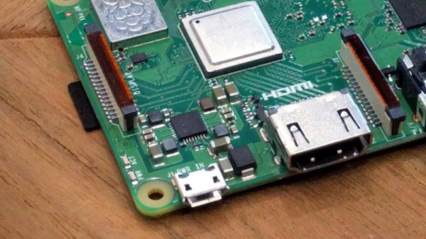
Since the Raspberry Pi 3B+ release, the Pi boards we all know and love gained one more weakpoint – the PMIC chip, responsible for generating all the power rails a Pi needs. Specifically, the new PMIC was way more vulnerable to shorting 5V and 3.3V power rails together – something that’s trivial to do on a Raspberry Pi, and would leave you with a bricked board. Just replacing the PMIC chip, the MxL7704, wouldn’t help since the Raspberry Pi version of this chip is customized – but now, on Raspberry Pi forums, [Nefarious19] has reportedly managed to replace it and revive their Pi.

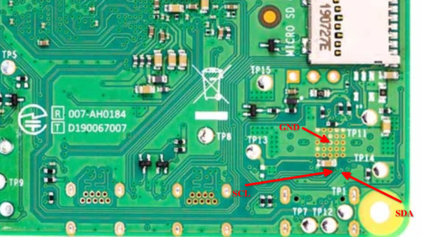
First off, you get a replacement PMIC and reflow it – and that’s where, to our knowledge, people have stopped so far. The next step proposed by [Nefarious19] is writing proper values into the I2C registers of the PMIC. For that, you’d want a currently-alive Pi – useful as both I2C controller for writing the values in, and as a source of known-good values. That said, if you go with the values that have been posted online, just having something like a Pi Pico for the I2C part ought to be enough.

[Nefarious19] reports a revived Pi, and this is way more hopeful than the “PMIC failures are unfixable” conclusion we’ve reached before. The instructions are not quite clear – someone else in the thread reports an unsuccessful attempt doing the same, and it might be that there’s a crucial step missing in making the values persist. However, such an advancement is notable, and we trust our readers to take the lead.

A week ago, [Mangy_Dog] on Hackaday Discord brought up fixing Raspberry Pi boards – given that the Raspberry Pi shortages are still an issue, digging up your broken Pi and repairing it starts making sense budget-wise. It’s no longer the ages where you could buy broken Pi boards by the hundred, and we imagine our readers have been getting creative. What are your experiences with fixing Raspberry Pi boards?

Shorting Pins On A Raspberry Pi Is A Bad Idea; PMIC Failures Under Investigation

You may have noticed, we’re fans of the Raspberry Pi here at Hackaday. Hardly a day goes by that we don’t feature a hack that uses a Pi somewhere in the build. As useful as the Pis are, they aren’t entirely without fault. We’ve talked about the problems with the PoE hat, and multiple articles about keeping SD cards alive. But a new failure mode has popped that is sometimes, but not always, caused by shorting the two power rails on the board.

The Pi 3 B+ has a new PMIC (Power Management Integrated Circuit) made by MaxLinear. This chip, the MxL7704, is a big part of how the Raspberry Pi foundation managed to make the upgrades to the Pi 3 without raising the price over $35.

A quick look at the Raspberry Pi forum shows that some users have been experiencing a specific problem with their new Raspberry Pi 3 B+ units, where the power LED will illuminate but the unit will not boot. The giveaway is zero voltage on the 3v3 pin. It’s a common enough problem that it’s even mentioned in the official boot problems thread.

Make sure the probe you are measuring with does not slip, and simultaneously touches any of the other GPIO pins, as that might instantly destroy your PI, especially shorting the 3V3 pin to the 5V pin will prove to be fatal.

Continue reading “Shorting Pins On A Raspberry Pi Is A Bad Idea; PMIC Failures Under Investigation”

Sonoff Postmortem Finds Bugs, Literally

While nobody is exactly sure on the exact etymology of the term, Thomas Edison mentioned some of his inventions being riddled with “bugs” in a letter he wrote all the way back to 1878. In the context of computers, any loyal Hackaday reader should know Grace Hopper’s infamous account of a moth being caught in an early electromechanical computer’s relays. To this pantheon of troublesome insects, we would humbly summit the story of a Sonoff TH16 switch being destroyed by a lowly ant.

According to [CNX Software], the Sonoff TH16 had been working perfectly for a year and a half before the first signs of trouble. One day the switch wouldn’t respond to commands, and a power cycle didn’t seem to clear the issue. Upon opening up the device to see what had gone amiss, it was clearly apparent something had burned up. But upon closer inspection, it wasn’t a fault with the design or even a shoddy component. It was the product of an overly curious ant who got a lot more than he bargained for.

Consulting the wiring diagram of the Sonoff, it appears this poor ant had the terrible misfortune of touching the pins of a through hole capacitor on the opposite side of the board. Bridging this connection not only gave him a lethal jolt, but apparently caused enough current to surge through a nearby resistor that it went up in smoke.

Now, some might wonder (reasonably so) about the conditions in which this switch was operating. If bugs could climb into it, it’s not unreasonable to assume it wasn’t well protected from the elements. Perhaps damp conditions were to blame for the failure, and the image of the ant “riding the lighting” is nothing more than a coincidence. Maybe. But sometimes you just gotta believe.

Incidentally, if you’d like to learn more about the woman who helped secure “bugs” in the IT lexicon, here’s a good place to start.

Ed Note: If you think you’re having deja vu all over again, we did point to this story in the Sunday Links roundup, but the graphics are just so good we couldn’t resist running it in full.

Fail Of The Week: Marginally Documented Pad Shorts To Maskless PCB

[Erich Styger] was bit by a nasty gotcha when soldering a QFN surface mount chip. The problem rears its ugly head when combining a chip possessing a padless conductor and a PCB without a solder mask. As you can see in the image above, there is a conductor exiting the side of the plastic QFN, but there is no pad associated with it. For this reason, you won’t see the conductor documented in the datasheet as a pin. It is documented in the mechanical drawing of the package, without any explicit reference to its existence. This is the Jason Bourne of package quirks.

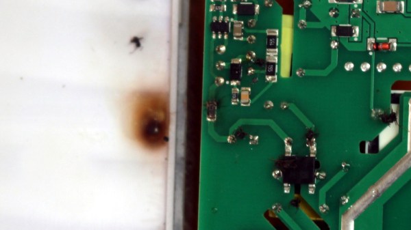
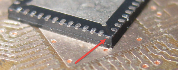
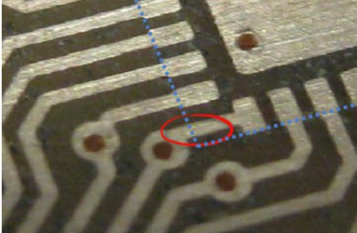
The PCB layout just happens to have a trace exiting right under this conductor. The two aren’t touching, but without solder mask, a bit of melted metal was able to mind the gap and connect the two conductors. [Eric] notes that although the non-pad isn’t documented, it’s easy to prove that it is connected to ground and was effectively pulling down the signal on that trace.
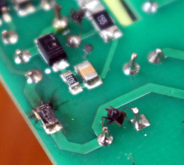
In a recent article on Hackaday I talked about “dangling pointers” and the challenge when interrupts expose the bug. [Erich’s] covered a ton of posts about embedded software. I was doing some poking around and was delighted to find that he covered the same concept and a solution for it using a program called cppcheck.

Painting A Wall With Light Using Water As Ink

This art installation uses a fantastic concept. The wall can be painted using water as ink which lights up a huge grid of white LEDs. This offers a very wide range of interactive possibilities since water can be applied in so many ways. Grab a paint brush, wet your finger, use a squirt gun, or mist with a spray bottle and the lights will tell you where you hit the wall.

We’re hoping a reader who speaks both French and English might help out by posting a translation as a comment on the prototyping video. In it, [Antonin Fourneau] shows off the various prototypes that led to the final product and we’d love to know what he’s saying. But by seeing the prototypes, then watching the English promo video after the break we can make a pretty good guess.  The boards have a hole that fits the flat-lens LEDs perfectly. This creates a mostly water tight seal to keep the liquid on one side while the leads are safe on the other. The water side has squiggly pads which allow droplets of water to complete an electrical connection.

Continue reading “Painting A Wall With Light Using Water As Ink”

Making A Smaller Keyboard

The keyboard on [Marek’s] laptop stopped working. He didn’t want to buy a replacement so he decided to start using an external keyboard. But hauling around a full 104-key model is a bit of a pain so he decided to make himself a shorter keyboard. He basically chopped off the 10-key pad on the right side of the board. This had the unexpected consequence of removing the screws that hold the top and bottom of the case together so he ended up adding a few extra screws to shore it up. You may be wondering how the key matrix still works if a portion of it has been cut off. [Marek] used the simple trick of folding the extra part of the membrane over and covering the unused contacts with some tape.

If you try this you should consider getting rid of the directional arrows and editing keys as well. There must be a way to map those keys elsewhere. Perhaps the half-qwerty keyboard hack will give you some inspiration for that.