Most readers of this site are familiar by now with the OpenSCAD 3D modeling software, where you can write code to create 3D models. You may have even used OpenSCAD to output some STL files for your 3D printer. But for years now, [nophead] has been pushing OpenSCAD further than most, creating some complex utility and parts libraries to help with modeling, and a suite of Python scripts that generate printable STLs, laser-ready DXFs, bills of material, and human-readable assembly instructions complete with PNG imagery of exploded-view sub-assemblies.
Recently [nophead] tidied all of this OpenSCAD infrastructure up and released it on GitHub as NopSCADlib. You can find out more by browsing through the example projects and README file in the repository, and by reading the announcement blog post on the HydraRaptor blog. Some functionality highlights include:
- a large parts library full of motors, buttons, smooth rod, et cetera
- many utility functions to help with chamfers, fillets, precision holes, sub-assemblies, and BOM generation
- Python scripts to automate the output of STLs, DXFs, and BOMs
- automatic creation of documentation from Markdown embedded in your OpenSCAD files
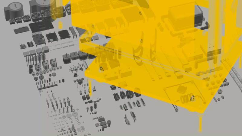
- automatic rendering of exploded subassemblies
All that’s missing is a nice Makefile to tie it all together! Try it out for your next project if you – like us – get giddy at the thought of putting your 3D projects into version control before “compiling” them into the real world.
We’ve discussed some complex OpenSCAD before: Mastering OpenSCAD Workflow, and An OpenSCAD Mini-ITX Computer Case.


Awesome work NOPhead. Your input to OpenSCAD community is greatly appreciated.
Thanks, Rob
Nice work and I’m sure a lot of effort has gone into it, so I’m keen to try it out and will do so soon. However something seems lacking though: the Gallery, which is the first thing I go to on a GitHub project. All the renders are finished equipment boxes that look much the same. If you only happened upon the Gallery you might wonder if the library is merely a box generator? If I needed a beer thermostat box I would go straight to Thingiverse and just use any one of the many box generators there.
The real nuggets – the primitives, tantalisingly mentioned above – like fillets, chamfers, buttons, precision holes (puzzled as to what that is as aren’t all CAD-generated holes precision holes?) are buried somewhere in the library, where they are the real jewels to be showcased. If there was a Gallery screenshot of each these primitives with the simplest possible example and a reference to where that is, I know I would find that most useful. And a cross-reference from the code function to see the relevant gallery picture. I know there’s the complete kitchen-sink image of all the bits layed out, but that’s not a key to how to use them individually.
Just like the OpenSCAD help pages themselves, where they present a single-purpose tiny snippet and the graphical results right next to it so the user can grasp the concept quickly and get on with their drawing.
Oh my – that is one very nice OpenSCAD library!
Thanks for making it public.
“If there was a Gallery screenshot of each these primitives with the simplest possible example and a reference to where that is, I know I would find that most useful. ”
There is exactly that on the main page, e.g.: https://github.com/nophead/NopSCADlib#Polyholes
“All that’s missing is a nice Makefile to tie it all together! ”
There is make_all.py that looks at the dependencies of a project and builds what is necessary.
Thanks for updating. That’s more what I was after.
Admirable effort by an esteemed figure in the community, but fundamentally what breaks OpenSCAD is:
1) lack of a solver, necessitating the reinvention of intersection code
2) No way to dimension, either for human consumption or for further calculation by an OpenSCAD script
3) CGAL, which is a mess of a kernel
4) No support for exporting AMF slice format
5) No support for STEP import/export
The list goes on…
Any attempt to put a “clean” interface over the OpenSCAD can never succeed.
None of these features or flaws will ever be addressed by the developers.
OpenSCAD has had its run.
That said, I still use it because it is easily vimable and come from the days of writing vertex coordinates on paper.
I agree with your list of the problems, but OpenSCAD has one thing that outweighs a lot of deficiences: your design is code, written in plain text and probably it’s parametric even if you haven’t tried well, simply because it’s almost a requirement. So OpenSCAD designs are never complete, they live on.
So, to summarize, OpenSCAD is totally useless, except for those things you keep it around to use it for. Got it.
Also, are you aware that you can export OpenSCAD models to other formats that can be used in other CAD applications? Allow me to introduce your idea of a tool kit, in which there are multiple tools, each with its uses. What’s the point of telling us all of the things you can’t do with a screwdriver?
Openscad has no viable export for solid models that are physically accurate and inter-operable with other cad packages. STLs are not accurate 3D models they are an approximation, while dxf is really only good for 2d line work. STEP is the industry standard for file exchange between CAD packages, its an ISO standard for the encoding of CAD data in plain text.
If open source cad is your thing Freecad is a more usable piece of software then openscad, that also make sharing cad data easy through its support of STEP files.
Freecad can import OpenSCAD files, so if you are advocating that I don’t think your first point is valid.
No, still valid because its not exporting a Step file. Its not exporting anything from its closed sand box to a universal interchange format like step. Some one took the time to write a openscad utility for freecad specifically to read a proprietary cad format . Contrast that to sharing data on a standard format like step that every major CAD package supports. I do not need a custom solid works , nx12, space claim, or any other type of cad format utility if they support step import/export functionality.
More to the point you can not send openscad files to machine shop for mill/ turn operations and you would not send a stl unless you want to get laughed out of the shop. Openscad can only produce real things via 3d printers or 2D cutting like laser or router cnc tables.
If your cad package exports STEP you are instantly inter-operable with the majority of the world, because its a standard. Openscad is like text editor that refuses to use ASCI or UTF-8 text encoding , instead has its own text encoding format that no one else uses and it can’t be bothered to export UTF-8 either.
If you create a cylinder in OpenSCAD, read it into Freecad and export it as STEP it will be a true cylinder, but then that isn’t an accurate representation of what the model in OpenSCAD was.
OpenSCAD doesn’t model in that way, it always produces polyhedral meshes, so nothing is lost exporting to STL. And my 3D printers only move in straight lines anyway.
If all my models are polyhedra, representing them in STEP would either be exactly the same as STL or an inaccurate representation just as a cylinder exported via Freecad is. Cylinders are actually polygonal prisms in OpenSCAD and I specify exactly how many vertices they should have and where they are.
“Openscad can only produce real things via 3d printers or 2D cutting like laser or router cnc tables.” And that is exactly what I use it for.
I also have a CNC lathe, I am building a laser cutter and will probably build a resin printer. Openscad will work fine for all of those as well, so why do I need something that exports STEP?
I never send anything to a machine shop because I have my own, so I won’t get laughed at. I laugh at them because with their expensive kit they can’t handle STL files but my homemade machines can.
OpenSCAD is fundamentally different from other 3D CAD packages, which is why, as a programmer, I prefer it. Nobody advocates anybody else should use it if they don’t want to. It is for people that prefer to express objects in code rather than a GUI.
“It is for people that prefer to express objects in code rather than a GUI.”
Yeah you do realize this is possible in every major CAD package, like NX 11, Autodesk Inventor, etc. I literally have programmed CAD models in “code” to work with Matlab when the complexity warranted it and the problem was nonlinear.
“If you create a cylinder in OpenSCAD, read it into Freecad and export it as STEP it will be a true cylinder, but then that isn’t an accurate representation of what the model in OpenSCAD was.”
SO Openscad can not model true geometric primitives, that is terrible.
“I laugh at them because with their expensive kit they can’t handle STL files but my homemade machines can.”
Oh they can mill they will just charge you a fortune for it because its terribly inefficient to generate tool paths from an STL.
Please explain to me how I can go from idea to printable STL with nothing more than a text editor in one of those other packages, and you might have something.
But since you put code in quotes, you and I both know it’s not the same thing at all.
From Autodesk Inventor:
This sample demonstrates the creation of primitive (solid) BRep.
‘ Set a reference to the TransientBRep object.
Dim oTransientBRep As TransientBRep
Set oTransientBRep = ThisApplication.TransientBRep
‘ Create a range box that will define the extents of a block.
Dim oBox As Box
Set oBox = ThisApplication.TransientGeometry.CreateBox
‘ Expand in all directions by 1 cm.
oBox.Expand 1
‘ Create the block.
Dim oBody As SurfaceBody
Set oBody = oTransientBRep.CreateSolidBlock(oBox)
‘ Create bottom and top points for a cylinder.
Dim oBottomPt As Point
Set oBottomPt = ThisApplication.TransientGeometry.CreatePoint(0, 1, 0)
Dim oTopPt As Point
Set oTopPt = ThisApplication.TransientGeometry.CreatePoint(0, 3, 0)
‘ Create the cylinder body.
Dim oCylinder As SurfaceBody
Set oCylinder = oTransientBRep.CreateSolidCylinderCone(oBottomPt, oTopPt, 0.5, 0.5, 0.5)
‘ Boolean the bodies; “oBody” will return the result
Call oTransientBRep.DoBoolean(oBody, oCylinder, kBooleanTypeUnion)
‘ Create a base feature with the result body.
Dim oBaseFeature As NonParametricBaseFeature
Set oBaseFeature = oCompDef.Features.NonParametricBaseFeatures.Add(oBody)
‘supports stl and bunch of export options
TranslatorAddIn.SaveCopyAs( SourceObject As Object, Context As TranslationContext, Options As NameValueMap, TargetData As DataMedium )
“But since you put code in quotes, you and I both know it’s not the same thing at all.”
Looks like code to me. Even has Boolean function like Openscad.
I use to write models in code when I had some super complex part in the automotive sector that needed to be tuned through simulation. I would do about 20 iterations in a day optimizing various aspects.
So why are people who apparently have no use for OpenSCAD reading and commenting on an article about OpenSCAD?