Now as far as problems go, selling so many products on Tindie that you need to come up with a faster way to test them is a pretty good one to have. But it’s still a problem that needs solving. For [Eric Gunnerson] the solution involved finding a quick and easy way to produce wooden pogo test jigs on his laser cutter, and we have a feeling he’s not the only one who’ll benefit from it.
 The first step was exporting the PCB design from KiCad into an SVG, which [Eric] then brought into Inkscape for editing. He deleted all of the traces that he wasn’t interested in, leaving behind just the ones he wanted to ultimately tap into with the pogo pins. He then used the Circle tool to put a 0.85 mm red dot in the center of each pad.
You’re probably wondering where those specific parameters came from. The color is easy enough to explain: his GlowForge laser cutter allows him to select by color, so [Eric] can easily tell the machine to cut out anything that’s red. As for the size, he did a test run on a scrap of wood and found that 0.85 mm was the perfect dimensions to hold onto a pogo pin with friction.
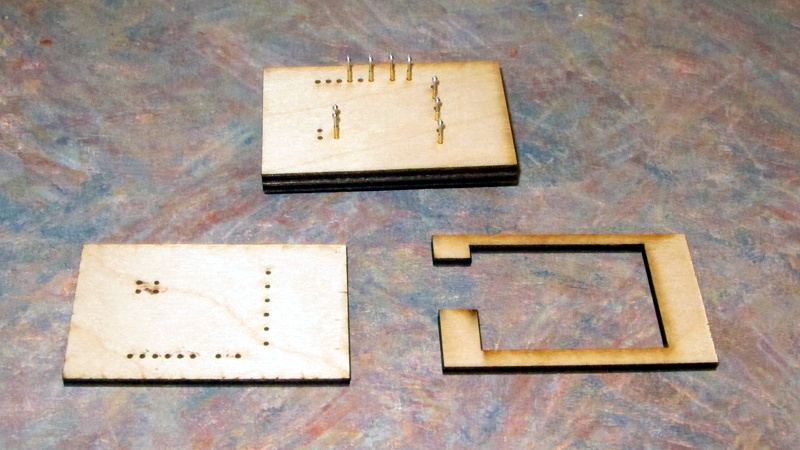
[Eric] ran off three identical pieces of birch plywood, plus one spacer. The pogo pins are inserted into the first piece, the wires get soldered around the back, and finally secured with the spacer. The whole thing is then capped off with the two remaining pieces, and wrapped up in tape to keep it together.
Whether you 3D print one of your own design or even modify a popular development board to do your bidding, the test jig is invaluable when you make the leap to small scale production.


I’ve cnc-drilled mine using the ncdrill file from the pcb and nylon for the base, and 3d printed one as well. The former was more durable but the latter was way more convenient. Laser-cutting it is a really swank idea, although I wonder about how long that thin plywood will hold the pogo pins securely. (Easily solved by getting long tail pins and stacking up a bunch of layers of plywood, though.) Nice build, and I’ll copy this at some point.
I would fill the area within spacer with some epoxy to secure the pins. One could even use some epoxy on the holes to glue the pins in place…
Pogopins break sometimes, if you use something like OpenFixture (or a second board) instead, you’ll be happy to be able to quickly replace pogopins one-by-one instead of staring at your test jig and figuring out how to best remove that epoxy layer. Alternatively, use pogo pin sockets =)
and we have find a pogo pin website,they have all kinds of Pogo Pin design drawing.maybe they can help you.
If you need pogo pin connector factory ,they can provide the samples for your test
https://www.pogo-pins.com/
Pogo Pin
You could program microcontrollers too. Great idea.
Another way that I learned from the HaD comments section: Use your PCB design to make two more boards but don’t populate them with parts. Drill through the test points on both boards. Separate the boards with male-female hex spacers, male side pointing up. Screws under the bottom board into the spacers, nuts holding the top board in place. Slide the pogos through the first board, solder to the second. Result, perfectly aligned pogo pins. This leaves conductive paths between pins so if that is an issue break those with a sharp knife.
that’s briliant idea. thanks
This is a cool idea, but for our newer designers out there, having done something like this before… the best way is to just make a custom pogo board with all the test points broken out to a header. It’s not expensive, easy to solder, easy to use, looks super professional. There is nothing, and I mean nothing! worse then designing an awesome board then thinking your design is messed up when really it’s your test setup. I’ve experienced it on one of my first boards and it sucked.
How do you do this in say KiCAD? (Break out the test points to a header.) Do you copy and reimport the Gerber?
Just check openfixture out! https://hackaday.com/2016/10/23/openfixture-takes-the-pain-out-of-pogo-pins/