Showing a board with a Pi Pico plugged into it, a USB-A socket marked "USB host", and a character display that says "PASSED" referring to the board being the brains of a testing jig.

USB Host On RP2040 – With PIO

Folks from [Adafruit] are showing off a neat hack – USB host on RP2040, using the now-famous PIO peripheral. [Adafruit] builds a lot of RP2040 boards, and naturally, you gotta test them before you ship them to customers. They’ve been using very specific Teensies for that, and at some point, those became unobtainium. Based on the work of [sekigon-gonnoc] and with help of [Thach], they’ve made their TinyUSB library support bitbanging of USB over PIO, and successfully ported their test jig firmware to it!

The base Pico-PIO-USB repo by [sekigon-gonnoc] shows a pretty impressive state of affairs – with low-speed and full-speed USB host and full-speed USB device modes supported, and quite a few examples to get you started. [Adafruit]’s work integrates this code into their TinyUSB stack, specifically focusing on MST (mass storage) features – as this is what you need to program a RP2040. Of course, they also provide a mass storage example to boot!

Test jigs are pretty important to have when making multiple pieces of a board, and with RP2040 supporting more and more interfaces thanks to PIO, it sounds like the perfect chip for your next production testing-intended PCB. With the jig brains taken care of, you’ll want to look into building no less important mechanical part, and we’ve covered quite a few ways to sort that out – here’s an OpenSCAD script that generates lasercutting files out of KiCad boards, or a jig built out of scrap copperclad FR4, and a pretty extensive tutorial on making your own lasercuttable jigs, to boot.

Continue reading “USB Host On RP2040 – With PIO”

Production PCB And Pogo Pins Produce A Clever Test Jig

[Hans Summers] runs a site qrp-labs.com, selling self-assembly kits mostly for radio gear and GPS applications, and had some production problems with his QCX-mini QRP transceiver kit. They were using an assembly house that had some problems with a sub-contractor going under during the pandemic, and the replacement service was somewhat below the expected level of quality, resulting in a significant number of SMT populated boards coming out non-functional. Obviously, not wanting to pass these on to customers as a debug problem, they set to work on an in-house QA test jig, to give them the confidence to ship kits again. The resulting functional test jig, (video, embedded below) takes a fairly interesting approach. Skip the video to 9:00 for the description of the test jig and detailed test descriptions.

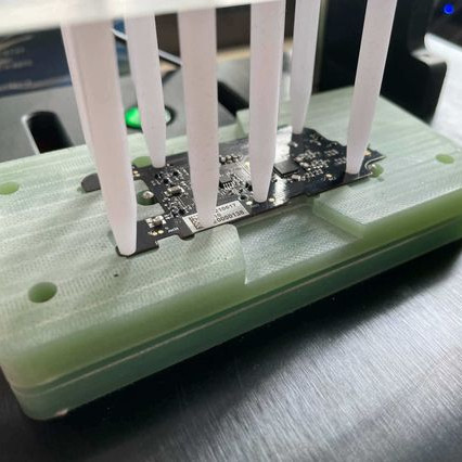
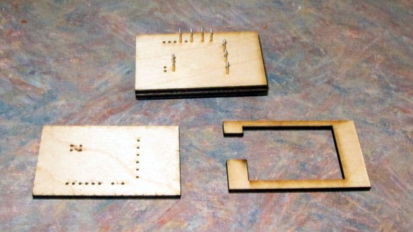
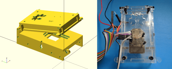
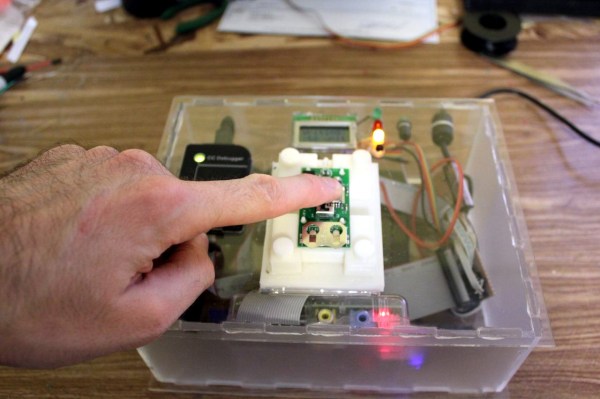
By taking an existing known-good PCB, stripping off all the SMT parts, and moving the through hole components to the rear PCB side, pogo pins could be soldered to strategic locations. Building the assembly into a rudimentary enclosure made from sawn-up raw copper clad board, with the pogos facing upwards, and a simple clamp on top, allowed the PCB-under-test (let’s call it the UUT from hereon) to be located and clamped in place. This compressed the pogos in order to make a firm electrical contact. A piece of MDF that had been attacked with a dremel did duty as a pressure plate, with cutouts around the SMT component areas to achieve the required uniform board pressure and keeping the force away from the delicate soldered parts. All this means that with an UUT connected via pogo pins to a through-hole only test PCB, the full circuit would be completed, if and only if the UUT was completely functional, and that means defect-free soldering and defect-free components.

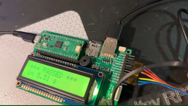
Next the firmware was rewritten to do duty as the test controller, which when powered up would step through a sequence of test scenarios and measurements, logging the results to an OLED display and a serial interface. This rig survived 1,000 SMT tests without failing, giving [Hans] the confidence to ship out new kits and providing a database of datalog results as a backup should a customer have an issue during final assembly. All-in-all a smart idea to solve a difficult problem, with nary a custom test jig PCB in sight!

These pages have been graced with many a pogo-based test rig over the years. Here’s one to start, and if you’ve got a handy laser cutter and some scrap wood, making an accurate test rig is no bother either.

Continue reading “Production PCB And Pogo Pins Produce A Clever Test Jig”

How The Flipper Zero Hacker Multitool Gets Made And Tested

Flipper Zero is an open-source multitool for hackers, and [Pavel] recently shared details on what goes into the production and testing of these devices. Each unit contains four separate PCBs, and in high-volume production it is inevitable that some boards are faulty in some way. Not all faults are identical — some are not even obvious —  but they all must be dealt with before they end up in a finished product.

One of several custom test jigs for Flipper Zero. Faults in high volume production are inevitable, and detecting them early is best.

Designing a process to effectively detect and deal with faults is a serious undertaking, one the Flipper Zero team addressed by designing a separate test station for each of the separate PCBs, allowing detection of defects as early as possible. Each board gets fitted into a custom test jig, then is subjected to an automated barrage of tests to ensure everything is as expected before being given the green light. A final test station gives a check to completed assemblies, and every test is logged into a database.

It may seem tempting to skip testing the individual boards and instead just do a single comprehensive test on finished units, but when dealing with production errors, it’s important to detect issues as early in the workflow as possible. The later a problem is detected, the more difficult and expensive it is to address. The worst possible outcome is to put a defective unit into a customer’s hands, where a issue is found only after all of the time and cost of assembly and shipping has already been spent. Another reason to detect issues early is that some faults become more difficult to address the later they are discovered. For example, a dim LED or poor antenna performance is much harder to troubleshoot when detected in a completely assembled unit, because the fault could be anywhere.

[Pavel] provides plenty of pictures and details about the production of Flipper Zero, and it’s nice to see how the project is progressing since its hyper-successful crowdfunding campaign.

Laser Cutting Wooden Pogo Pin Test Jigs

Now as far as problems go, selling so many products on Tindie that you need to come up with a faster way to test them is a pretty good one to have. But it’s still a problem that needs solving. For [Eric Gunnerson] the solution involved finding a quick and easy way to produce wooden pogo test jigs on his laser cutter, and we have a feeling he’s not the only one who’ll benefit from it.

The first step was exporting the PCB design from KiCad into an SVG, which [Eric] then brought into Inkscape for editing. He deleted all of the traces that he wasn’t interested in, leaving behind just the ones he wanted to ultimately tap into with the pogo pins. He then used the Circle tool to put a 0.85 mm red dot in the center of each pad.

You’re probably wondering where those specific parameters came from. The color is easy enough to explain: his GlowForge laser cutter allows him to select by color, so [Eric] can easily tell the machine to cut out anything that’s red. As for the size, he did a test run on a scrap of wood and found that 0.85 mm was the perfect dimensions to hold onto a pogo pin with friction.

[Eric] ran off three identical pieces of birch plywood, plus one spacer. The pogo pins are inserted into the first piece, the wires get soldered around the back, and finally secured with the spacer. The whole thing is then capped off with the two remaining pieces, and wrapped up in tape to keep it together.

Whether you 3D print one of your own design or even modify a popular development board to do your bidding, the test jig is invaluable when you make the leap to small scale production.

OpenFixture Takes The Pain Out Of Pogo Pins

[Elliot] (no relation, but hey, cool name!) wrote in with his OpenFixture model for OpenSCAD. It’s awesome because it takes a small problem, that nonetheless could consume an entire day, and solves it neatly. And that problem is making jigs to test assembled electrical products: a PCB test fixture.

In the PCB design software, you simply note down the locations of the test points and feed these into the OpenSCAD model. ([Elliot] shows you exactly how to do it using KiCAD.) There are a few more parameters of the model that you can tweak to match your particulars, but you should have a DXF outline for a test jig in short order. Cut that out, assemble, and test.

If you have to make more than a few handfuls of a complicated circuit, it becomes worth it to start thinking about testing them systematically. And with this OpenSCAD model, you can have the test jig up and running before the first prototype boards are back in from the fab. How cool is that?

Tools Of The Trade – Test And Programming

In our final installment of Tools of the Trade (with respect to circuit board assembly), we’ll look at how the circuit board is tested and programmed. At this point in the process, the board has been fully assembled with both through hole and surface mount components, and it needs to be verified before shipping or putting it inside an enclosure. We may have already handled some of the verification step in an earlier episode on inspection of the board, but this step is testing the final PCB. Depending on scale, budget, and complexity, there are all kinds of ways to skin this cat.

Continue reading “Tools Of The Trade – Test And Programming”

Test Beds And Jigs With Pogo Pins

Pogo pins – spring-loaded pin contacts are pretty fun to play with and even cooler when they get used in electronic devices like Adafruit and SparkFun’s test jigs. Check after the break for how these two companies have created their own production hacks. Continue reading “Test Beds And Jigs With Pogo Pins”