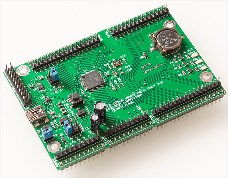
When [Andy Brown] recently tripped over ST’s new G0 series of MCUs, he figured after some research that the best way to learn everything there’s to know about the STM32G0xx by making his own development board based around the STM32G081. The result is a Nucleo-style board, breaking out all pins to convenient 2.54 mm headers, and with a number of niceties, such as an on-board coin cell and 32.768 kHz LSE oscillator for RTC use and three different power supplies (3.3 V, 2.5 V, and 1.8 V) for the MCU.
The board is programmed with an external ST-Link programmer that connects to the SWD interface on the MCU, with a 20-pin programming header provided. While by no means small or compact, it makes for very easy breadboarding and prototyping, with all 2.54 mm headers accessible from the bottom and top.
As for the STM32G0 series itself, the jury is still out on its performance compared to the F0. The former swaps the Cortex-M0 core for an M0+, with a reduced pipeline length (3 stages in the G0) but increased frequency (64 MHz versus 48 MHz). The G0 has a little bit more SRAM, but so far less Flash storage. According to ARM, this MCU range is designed to remove any need to still use an 8-bit MCU. Big claims, indeed.
The biggest issue which [Andy] had while developing this board was probably with the CH340 USB-UART chip. Ordering them from AliExpress as is common, the CH340G ICs he got just wouldn’t work on the first board revision, forcing him to switch to the CH340E and requiring a board respin. This version has an internal oscillator and as a bonus even came in the original tape packaging when it arrived, instead of in a plastic baggy like with the CH340G parts.
See a video of [Andy] going through the design after the break.
Now that the board is up and running, it’ll be interesting to see what kind of performance can be extracted from this new MCU range and whether it lives up to the hype. On [Andy]’s blog you can find the design files, gerbers and a complete BOM for the board, so that you can easily make your own.


Awaiting the stm32g47x
Honestly, even if the chip looks fine ARM development tools are truly horrible. With PIC16 or PIC18 and CCS C compiler I can develop extremly optimized code in a matter of hours, with arm-gcc I’d spend about the same time writing code and then week or two debugging compiler quirks, silicon glitches, datasheet mistakes etc.
Just because you’re not familiar with the dev tools doesn’t mean they are horrible. All embedded tools are a little horrible, but that’s beside the point.
People familiar with ST tools like CubeMX can get a project up and running under an hour.
If you ask most embedded developers, they wouldn’t have nice things to say about MP Lab and the PIC development tools.
Just because you’re not familiar with MPLAB and other PIC dev tools doesn’t mean they are horrible.
Do you still need to pay Microchip to get a compiler that has all the optimization options available?
CubeMX is one of the worst things to ever occur to humanity, cancer included
It compiles to huge over-abstracted nonsense that is undebuggable and wastes cycles left and right!
please do not ever use that as an exacmple of anythign good. I’ll take herpes over CubeMX!
At least CubeMX is curable.
OK. Space herpes!
I disagree. CubeMX is nowhere near as bad as you describe it. Actually I quite like it. It makes it much easier and faster to configure the clocks and peripherals. It helps less-experienced developers who would forget setting some registers because they do not yet know every detail of the peripherals they use.
By over-abstracted nonsense you are probably referring to the HAL libraries, right? They do kinda suck. But for most peripherals you can choose to use the Low-Layer drivers instead. LL is much better than HAL because the functions correspond more closely to the peripheral structure and functionality.
Been developing for 5 years on Cortex M4/M7
Never had a compiler bug, silicon glitch or data sheet mistake.
Once you understand how things work like : DCACHE, DMA, Timers, CMSIS DSP AND CMSIS RTOS then everything is dandy. With Dcache on and Opt 3 you can do a hella lot on a modern microcontroller.
People playing with PIC18 are missing out on a hella lot of performance and peripherals.. And bogging down their processor by spending time baby sitting peripherals instead of DMAing data in/out.
The thing I like about the ARM chips is that you can go to a different family for faster, larger memory or I/O, lower power. Or go side ways for a different series from same or different vendors that might have better peripherals.
It doesn’t have crazy restriction of code space or data space which requires silly declaration and access macros like AVR.
FYI: ST licensed Keil MDK for their STM32F0, STM32L0 and recently STM32G0 series with a free-to-use professional tool suite. For that reason alone, I am sticking with these chips.
http://www2.keil.com/stmicroelectronics-stm32/mdk
I find the STM development tools much better because they do not require an extra paying license (to have all features), and you have the choice to use open source GCC or alternatives (no vendor lock-in). Moreover, I found the MPLAB environment dreadful and painfully to use compared to the TrueStudio (Eclipse based)…
Somehow I don’t see any ARM based microcontroller being a suitable replacement for the 8-pin 8-bit ATTiny85 I am using in my current project…
These days you can find STM32’s in QFN 32 packages, which are almost the same size as the ATTiny85 PDIP, so why bother?
You are aware that attinys come in smt packages as well
And choose the approprate part for the job
First, due to the difficulty of soldering that qfn32 package in the place of the AtTiny85 pdip. Then, code diferences.
But it would be interesting to have a *real* STM32 in soic-8 package….easy fitting in a lot of places, like the attiny85 in that same package is.
You can get an Atmel SAMD9/10/11 in SOIC-14, I think that’s the closest on the market right now?
Not a bad little chip all considered.
Though I would *love* to see an ARM variant of the ever-popular ’85 series.
If someone can show me an STM32 that plugs into a breadboard like my ATTiny85, sips as little power as my ATTiny85 and is as cheap as my ATTiny85, that would be great. Otherwise I dont see how an STM32 is a viable replacement :)
There is the LPC810M021FN8 in DIP8. It is limited to 4KB FLASH/1KB RAM + 2 USART, SPI, I2C. The other packages with a larger die size have 2x – 4x memory.
ST says they’ll have an 8-SON version in the coming months. Only up to 32KB Flash / 8KB RAM though:
https://blog.st.com/stm32g0-mainstream-90-nm-mcu/
I dunno, I really like this new series. It seems like a reliable workhorse, it can run at 1.8V, and it has some nice improvements over older STM32s such as a more configurable DMA and easier hardware layout (no mandatory BOOT0 pin!)
The only thing it’s missing is USB, although it can still do type-C power delivery.
Could be useful something like this, with usb. Use the four pins of one side for the 4 pins of usb, and leave the 4 on the other side for configurable uses ….
ST had started to move away from wasting a pin with BOOT0 already, for example the F042 muxed it with a GPIO. The pin layout on the G0 is far more sensible all round. At last.
Perhaps not for your project, but those running on battery power will be looking closely at it. According to ST: “the STM32G0 requires less than 100 µA / MHz when running at 64 MHz”. What do you get out of the ATTiny?
Do i see a mini usb connector? Yay. The last year I try to avoid the flimsy micro usb.
Flimsy?
The micro-USB connector is more reliable than the mini-USB connector. The mini has its clamping springs in the equipment side socket, so when the springs wear out, the socket must be replaced. The micro has its clamping springs on the cable connector, if they wear out, you just replace the cable.
I think mini was rated for 10,000 cycles and the micro for 100,000 cycles.
and USB-C for even more
I like MicroUSB because I can get the replacement connectors + housing really cheap from Aliexpress.
Really…
I was looking at a damaged USB cable earlier today and thought it would be neat if a replacement connector was available.
Something like this: https://www.aliexpress.com/item/32823313398.html
Look at similar part from other vendors. Sometimes there are hidden treasures or cheaper alternatives that the search doesn’t turn up. <3 the Micro USB breakout PCB.