Jana showing the board in action, with a magnetic probe attached to it

Add The Analog Toolkit To Your…Toolkit

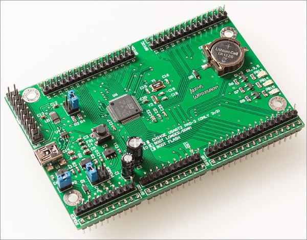
Analog acquisition tools are super helpful whenever you want to run an experiment, test out a theory, or improve upon your code, and you won’t realize how much you always needed one up until you’re facing a situation where it’s the only tool for the task. Well, here’s a design you might just want to add to your next PCB order — the STM32G4 Analog Toolkit from [Jana Marie].

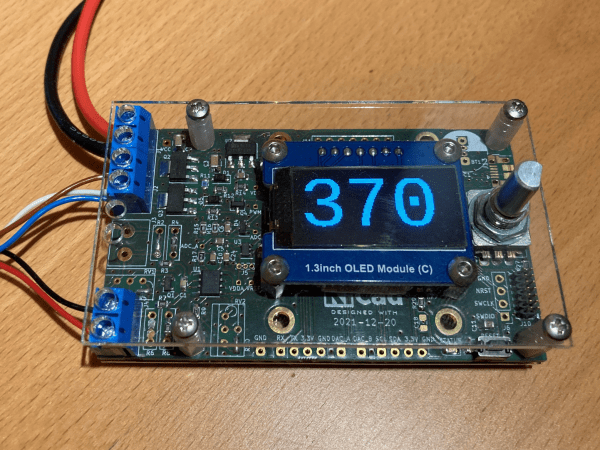
The recommended STM32G431 is a wonderful tool for the task in particular. For a start, this board exposes nine 16-bit ADC inputs, with six of them capable of differential mode and three of them having the PGA (Programmable Gain Amplifier) feature. There’s also two 12-bit DAC pins, two timer outputs, three GPIOs, and UART with I2C for the dessert. As a bonus, it can work as a PD trigger, giving you higher-than-5V voltages out of USB-C for any experiments of yours.

The board requires only a few components, most of them easily solderable, with the STM32 in the TQFP32 package. The BOM is optimized, the GPIOs are used up to the max, with two spare GPIOs driving an RGB LED using a witty control scheme. There’s even a place to clip an alligator clip, in case that’s what your probing hardware wants! All in all, this is a carefully crafted design certainly worth having on hand.

Make sure to get a few of these made before you find yourself desperately needing one! That said, there’s always a backup option, the venerable ATtiny85.

Another Neat General Purpose Soldering Iron Driver

Over on Hackaday.io, user [Tomasz Jastrzebski] has designed a tidy-looking custom controller for driving temperature-controlled soldering irons. The design is intended to be general purpose, capable of operating with irons rated for different voltages and probe type, be they thermocouple- or thermistor-based. Rather than integrating a power supply, this is handled by an external unit, giving the possibility of feeding this from a variety of sources that are not necessarily tied to the grid.

Hardware-wise, we’ve got the ubiquitous STM32 microcontroller in charge of the show, with a nice front end based on the INA823 instrumentation amplifier, referenced to a REF2030 precision voltage source. The input stage is configured as a versatile Wheatstone bridge input circuit, giving plenty of scope for tweaking.

There are a few extra features in the design that aren’t necessarily needed for a soldering iron driver, such as RTC support, complete with supercapacitor backup, but then this doesn’t have to drive a soldering iron, it could drive any DC heater with temperature feedback. With a change in firmware, this could serve other tasks. One potential feature that springs to mind — have the unit automatically power down at a certain time of day in case it was left on accidentally.

The schematic has a lot of relevant detail — in that many parts have a good list of alternatives, presumably because of the semiconductor shortages — which is a good habit to get into if you ask us. Many of us involved with manufacturing have been doing this for years, as it makes sense to give the assembly house the extra options, but this really is basically mandatory practice now.

Firmware for the STM32G0 series microcontroller is based on the STM32 HAL, keeping it simple, with a Visual Studio Code project provided for your convenience. All hardware (KiCAD) and firmware can be found on the project GitHub.

We’ve seen a few projects like this over the years, like this Really Universal Soldering Controller, a custom controller for JBC irons, and this great portable Arduino-based unit.

Wooden Linear Clock Aided By GPS

The notion of segmenting and quantizing the day into discrete segments of time is perhaps one of the most human things we do. Heralding back to a simpler era when a day was just a progression of sunrise to sunset, [James Wilson] created a beautiful linear clock that shows time as progress throughout the day.

For previous projects, [James] had used nixie tubes but the headache of the inverters, high voltages, and tight spaces led him to instead use mini-LED’s. Two PCBs were manufactured, one as the display and one to hold the GNSS module as it works best when mounted horizontally to point at the sky. Two rows of 112 tightly packed LEDs make a great stand-in for bar graph style tubes and are are controlled by TLC5926 shift registers. The venerable STM32G0 was chosen as the microcontroller to power the clock. With the help of some approximating functions and the location provided by the GNSS module [James] had the position of the sun which he then could turn into a % of progress through the sky.

The enclosure was modeled after the mid-century modern look and made of several pieces of wood CNC’d and then glued together. Machining it out of a solid piece of wood would have been difficult as finding long enough end mills that could carve out the interior is tricky. We think the resulting clock looks wonderful and the walnut accents the maple nicely.

The writeup is highly detailed and we love the honest explanations of what choices were made and why. The code is available on GitHub. Or if perhaps you’d rather eschew the LED’s and go for something more physical there’s always this ratcheting linear clock to draw inspiration from.

Building A Development Board For The STM32 G0 Series

When [Andy Brown] recently tripped over ST’s new G0 series of MCUs, he figured after some research that the best way to learn everything there’s to know about the STM32G0xx by making his own development board based around the STM32G081. The result is a Nucleo-style board, breaking out all pins to convenient 2.54 mm headers, and with a number of niceties, such as an on-board coin cell and 32.768 kHz LSE oscillator for RTC use and three different power supplies (3.3 V, 2.5 V, and 1.8 V) for the MCU.

The board is programmed with an external ST-Link programmer that connects to the SWD interface on the MCU, with a 20-pin programming header provided. While by no means small or compact, it makes for very easy breadboarding and prototyping, with all 2.54 mm headers accessible from the bottom and top.

As for the STM32G0 series itself, the jury is still out on its performance compared to the F0. The former swaps the Cortex-M0 core for an M0+, with a reduced pipeline length (3 stages in the G0) but increased frequency (64 MHz versus 48 MHz). The G0 has a little bit more SRAM, but so far less Flash storage. According to ARM, this MCU range is designed to remove any need to still use an 8-bit MCU. Big claims, indeed.

The biggest issue which [Andy] had while developing this board was probably with the CH340 USB-UART chip. Ordering them from AliExpress as is common, the CH340G ICs he got just wouldn’t work on the first board revision, forcing him to switch to the CH340E and requiring a board respin. This version has an internal oscillator and as a bonus even came in the original tape packaging when it arrived, instead of in a plastic baggy like with the CH340G parts.

See a video of [Andy] going through the design after the break.

Continue reading “Building A Development Board For The STM32 G0 Series”