It would be fair to say that the Raspberry Pi team hasn’t been without its share of hardware issues, with the Raspberry Pi 2 being camera shy, the Raspberry Pi PoE HAT suffering from a rather embarrassing USB power issue, and now the all-new Raspberry Pi 4 is the first to have USB-C power delivery, but it doesn’t do USB-C very well unless you go for a ‘dumb’ cable.
Join me below for a brief recap of those previous issues, and an in-depth summary of USB-C, the differences between regular and electronically marked (e-marked) cables, and why detection logic might be making your brand-new Raspberry Pi 4 look like an analogue set of headphones to the power delivery hardware.
A Trip Down Memory Lane
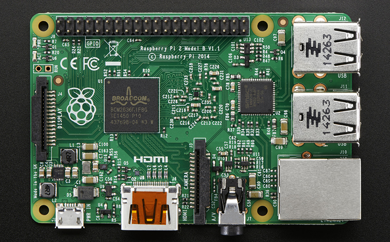
Back in February of 2015, a blog post on the official Raspberry Pi blog covered what they figured might be ‘the most adorable bug ever‘. In brief, the Raspberry Pi 2 single-board computer (SBC) employs a wafer-level package (WL-CSP) that performs switching mode supply functionality. Unfortunately, as is the risk with any wafer-level packaging like this, it exposes the bare die to the outside world. In this case some electromagnetic radiation — like the light from a xenon camera flash — enter the die, causing a photoelectric effect.
The resulting disruption led to the chip’s regulation safeties kicking in and shut the entire system down, fortunately without any permanent damage. The fix for this is to cover the chip in question with an opaque material before doing something like taking any photos of it with a xenon flash, or pointing a laser pointer at it.
While the Raspberry Pi 2’s issue was indeed hard to predict and objectively more adorable than dangerous, the issue with the Power over Ethernet (PoE) HAT was decidedly less cute. It essentially rendered the USB ports unusable due to over-current protection kicking in. The main culprit here is the MPS MP8007 PoE power IC (PDF link), with its relatively sluggish flyback DC-DC converter implementation being run at 100 kHz (recommended <200 kHz in datasheet). Combined with a lack of output capacity (41% of recommended), this meant that surges of current were being passed to the USB buffer capacitors during each (slow) power input cycle, which triggered the USB chipset’s over-current protection.
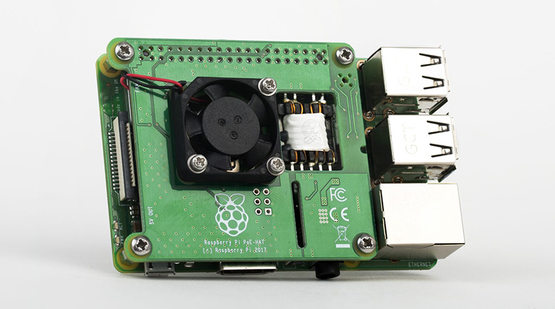
The solution here was a redesign of the PoE HAT, which increased the supply output capacitance and smoothed the output as much as possible to prevent surges. This fixed the problem, allowing even higher-powered USB devices to be connected. The elephant-sized question in the room was of course why the Raspberry Pi team hadn’t caught this issue during pre-launch testing.
USB Type-C is Far More Than Just a Connector
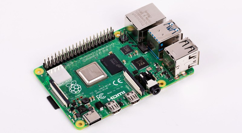
The new Raspberry Pi 4 was just released a few weeks ago, and is the biggest overhaul of the platform since the original Model B+ that defined the ‘Raspberry Pi form factor‘. But in less than a week we started hearing about a flaw in how the USB-C power input was behaving. It turns out the key problem is when using electronically marked cables which include circuitry used by the USB-C specification to unlock advanced features (like supplying more power or reconfiguring what signals are used for between devices). These e-marked cables simply won’t work with the Pi 4 while their “dumb” cousins do just fine. Let’s find out why.
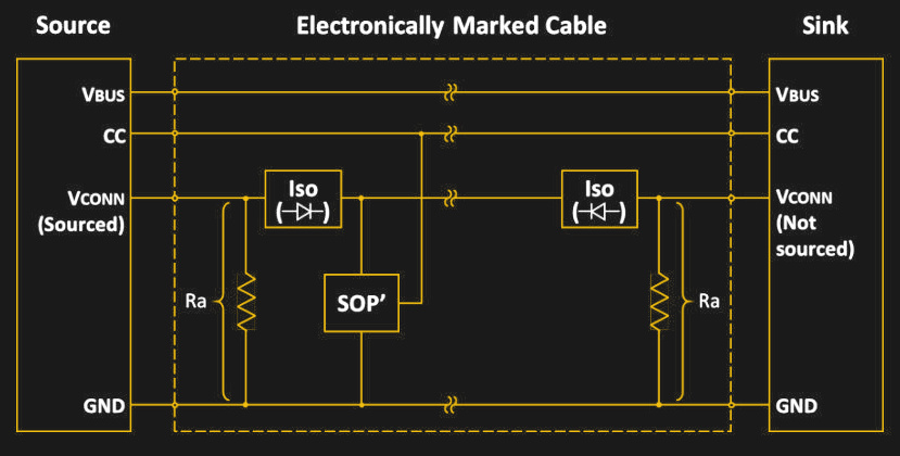
The USB-C specification is quite complex. Although mechanically the USB-C connector is reversible, electrically a lot of work is being performed behind the scenes to make things work as expected. Key to this are the two Configuration Channel (CC) pins on each USB-C receptacle. These will each be paired to either the CC wire in the cable or (in an e-marked cable) to the VCONN conductor. A regular USB-C cable will leave the VCONN pin floating (unconnected), whereas the e-marked cable will connect VCONN to ground via the in-cable Ra resistor as we can see in this diagram from the USB-C specification.
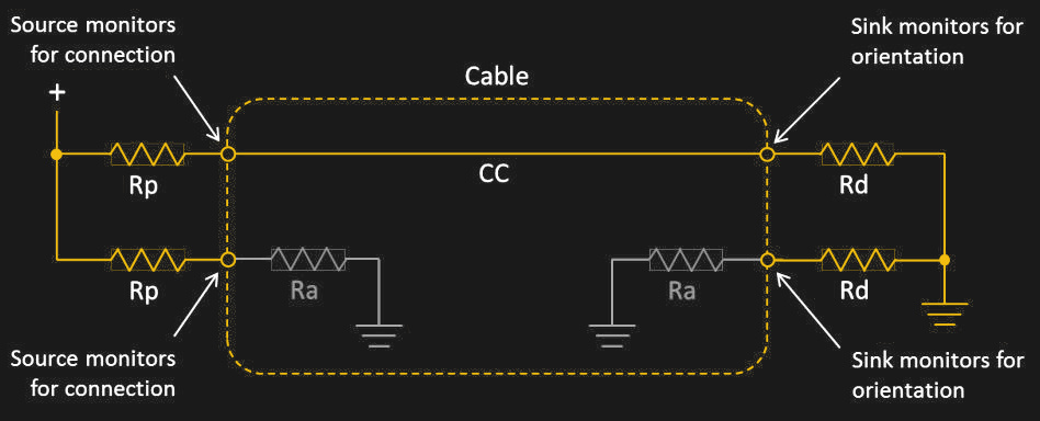
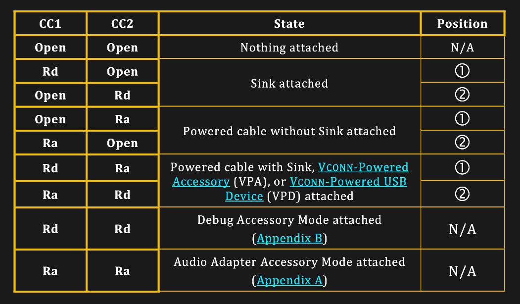
It’s also possible to have an e-marked USB-C cable without the VCONN conductor, by having SOP ID chips on both ends of the cable and having both the host and the device supply the cable with VCONN. Either way, both the host and device monitor the CC pins on their end measure the resistance present through the monitored voltage. In this case, the behavior of the host is dictated by the following table:
The Analog Raspberry Pi 4
Now that we have looked at what a basic USB-C setup looks like, it’s time to look at the subject of this article. As the Raspberry Pi team has so gracefully publicized the Raspberry Pi 4 schematics (minus the SoC side for some reason), we can take a look at what kind of circuit they have implemented for the USB-C sink (device) side:
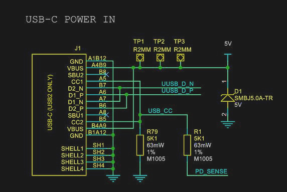
As we can see here, contrary to the USB-C specification, the Raspberry Pi design team has elected to not only connect CC1 and CC2 to the same Rd resistor, but also shorted CC1 and CC2 in the process.
Remember, the spec is looking for one resistor (Rd) on each of the two CC pins. That way, an electronically marked cable connecting the Pi 4 board and a USB-C charger capable of using this standard would have registered as having the appropriate Rd resistance, hence 3A at 5V would have been available for this sink device.
 Since this was however not done, instead we get an interesting setup, where the CC connection is still established, but on the Raspberry Pi side, the resistance doesn’t read the 5.1 kOhm of the Rd resistor, as there’s still the Ra resistor in the cable on the other CC pin of the receptacle. The resulting resistor network thus has the values 5.1k and 1k for the Rd and Ra resistors respectively. This circuit has an equivalent circuit resistance of 836 Ohm.
This value falls within the range permitted for Ra, and thus the Raspberry Pi 4 is detected by the source as Ra + Ra, meaning that it is an audio adapter accessory, essentially a USB-C-to-analog audio dongle. This means that the source does not provide any power on VBUS and the Raspberry Pi 4 will not work as it does not get any power.
In the case of a non-electronically marked cable, this would not be an issue as mentioned earlier, as it doesn’t do this form of detection, with no Ra resistor to get in the way of making the Raspberry Pi 4 do its thing.
Testing is More Important than Developing
Much like with the PoE HAT issue, the question was quickly raised: why wasn’t this issue with the Raspberry Pi 4’s USB-C port found much sooner during testing. Back with the Pi 2 PoE HAT, the official explanation from the Raspberry Pi team was that they had not tested with the appropriate devices, had cut back on testing because they were late with shipping and did not ask the field testers the right questions, leading to many scenarios simply not being tested.
In a response to Tech Republic, the CEO of Raspberry Pi Ltd, Eben Upton has admitted to the Pi 4 USB-C error. And a spokesperson for Raspberry Pi Ltd said in a response to Ars Technica that an upcoming revision of the Raspberry Pi 4 is likely to appear within the “next few months”.
It seems obvious how this error managed to sneak its way into production. Much like with the PoE HAT, a design flaw snuck in, no one caught it during schematic validation, the prototype boards didn’t see the required amount of testing (leaving some use cases untested), and thus we’re now seeing another issue that leaves brand new Raspberry Pi hardware essentially defective.
Sure, it’s possible to hack these boards as a workaround. With the PoE HAT one could have soldered on a big electrolytic capacitor to the output stage of the transformer’s secondary side and likely ‘fixed’ things that way. Similarly one could hack in a resistor on the Raspberry Pi 4 after cutting a trace between both CC pins… or even simpler: never use an e-marked USB-C cable with the Raspberry Pi 4.
Yet the sad point in all of this is undoubtedly that these are supposed to be ready-to-use, fully tested devices that any school teacher can just purchase for their classroom. Not a device that first needs a trip down to the electronics lab to have various issues analyzed and bodge wires and components soldered onto various points before being stuffed into an enclosure and handed over to a student or one’s own child.
The irony in all of this is that because of these errors, the Raspberry Pi team has unwittingly made it clear to many that testing hardware isn’t hard, it just has to be done.
Compliant USB-C is Not Easy
In the course of writing this article, yours truly had to dive deep into the USB-C specification, and as a point of fairness to the Raspberry Pi design team, the first time implementing USB-C is not a walk in the park. Of all specifications out there, USB-C does not rank very high in user-friendliness or even conciseness. It’s a big, meandering, 329 page document, which does not even cover the monstrosity that’s known as USB-C Power Delivery.
Making a mistake while implementing a USB-C interface during one’s first time using it in a design is not a big shame. The USB-C specification adds countless details and complexities that simply do not exist in previous versions of the USB standard. Having this mess of different types of cables with many more conductors does not make life easier either.
The failure here is that the USB-C design errors weren’t discovered during the testing phase, before the product was manufactured and shipped to customers. This is something where any team that has been involved in such a project needs to step back and re-evaluate their testing practices.


You left out the original USB issues that caused some devices (webcams in particular) to not work well. And the polyfuse issue. And attaching a usb hub to a usb hub fails, etc. I do like the raspberry Pi. I really hope they get it working properly.
“The obvious cause for why this error managed to sneak its way into production seems obvious.”
ACK.
That is awkward, I’ve edited that sentence for more clarity.
Obviously :)
Remember, it’s Trading that designs the boards, not the Foundation.
The thing is…the USB-C standard contains a plain old schematic that is supposed to be copied 1:1 into a devices schematic.
Which means that there would be absolutely no need for quality control for that functionality if they would’ve just stuck to what the standard says.
Which in turn means: All of this could have been avoided if the person responsible for that schematic wouldn’t have thought that they’re smarter than the USB-C definitions.
And that makes it even worse than bad QC would have been.
I wish people would implement the reference designs like that. I’m dealing with a $250,000 box at work and the idiots at the company that designed it (sorry, can’t say who) messed up the reference SDI implementation given in the chip design (they left out parts). The SDI interface didn’t work due to this and it took me (the customer) looking at the schematics to figure it out.
You are assuming that they actually read the specification. ;-) The authors of the USB Type-C Connector specification tried to include sufficient and detailed information to aid developers. In the case of the Raspberry PI 4, they figured out that an Rd was required to get a USB-C power supply to turn on 5V, but they failed to understand the additional interactions with cables that identified which of the CC!/CC2 pins to assign to be CC and which to apply Vconn (assuming an Ra was present in the cable and they wish to supply more then 3A).
By failing to identify CC they violate the USB Type-C Connector spec by not monitoring it for the USB C power supply’s USB Type-C current advertisement (500mA, 1.5A or 3A) and abiding by it.
I suspect during their development and testing process they only tused cables that were the USB 2.0 Type-C Cable Assemblies that are typically used with chargers without electronic marking . Shame on them, but hopefully they will read the entire spec before their next release that fixes the deficiencies.
Seems Meredith’s Axiom of software design also applies to hardware.
Nah, that’s bullshit. You cannot get anywhere near this sort of complexity of device with “zero quality control”, and nobody who has ever had to work on anything even vaguely non-trivial would ever make such a claim. Hardware is fucking hard, there are a million things that can go wrong, and it’s a herculean task just to get to market with a device that doesn’t have a 80% failure rate out of the factory. Getting from there to “zero detectable bugs” is so much harder than that, and there’s no magic procedure that will prove that you’ve found everything.
Finally, it’s an insanely cheap device intended for teaching computing skills to children. Have some perspective about the intended target and stop being salty for not getting a perfect supercomputer for five cents that is safe to use in medical equipment and can predict the future.
Agreed.
I spent 2+ years working in a lab on FMEDA analysis and HWIFI on embedded designs for a SIL 4 application. I can tell you, there is no such thing as “zero detectable bugs”.
In regards to re-evaluating the testing procedures pre-release, I imagine that the same team doing the design is also writing the design tests. Would be nice to have independence in this step, but like you said, its a learning device for kids that costs <50$.
You very much CAN get at exactly this level of fail with quality control that amounts to “Is it done? Okay, plug it in! Works…? Not a word more, we’re shipping it!”. And they are proving time and time and time again that is exactly the extent of what they can be bothered to do.
Here’s an idea for free quality control, open a beta testing group for about 100 members of the pi community that you ship the first batch to when you think it is ready. Wait a month and tell the community that the beta testers have the first batch so everyone is not left in the dark.
Done, ideally those in the beta group would get a discounted rate on the beta boards, but you could also have the boards at full price or even charge a fee to be part of the beta group and you would still have plenty of volunteers.
The sad thing is someone could probably take some time and make a j
The first generation Pi had another problem: there were two LDOs on the board with their outputs shorted together, feeding the same rail. IIRC, one LDO was was inside one of the ASICs.
Depending on tolerances, one LDO or the other would supply most of the current for that rail.
Only one had a heatsink though. If the one in the ASIC was supplying most of the current, it would overheat.
I can only assume that they didn’t read the datasheet thoroughly. It’s good to see some things don’t change.
It was the standalone 1.8V regulator for the SoC core and the 1.8V regulator in the USB hub/Ethernet chip. The USB chip regulator was meant to just power itself but somebody didn’t read the datasheets properly and hooked it up to the 1.8V net on the board. If due to process variation that the USB chip regulator was slightly higher voltage then it would end up powering the main SoC as well which caused it to get extremely hot.
Neither had a heatsink. But it did cause all the third party vendors to add a heatsink for the USB chip in their kits. It was only ever a problem with the initial revision or two of the RPi 1 so was completely superfluous for everything since then. Most of those heatsinks were crap anyway and actually made it worse because the “thermal tape” was just regular double sided tape like you’d find in an office supply store.
So do I cancel my order for a Pi4 or wait for the fix?
If you get the official power brick, it’s fine.
You can try out the cables and bricks you have, and see what works. The issue isn’t that it kills the pie, simply that it receives no power. Good, compliant USB-A to C cables should work fine off 2-3A bricks. Most USB2 USB-C cables are not e-marked, so they’ll also work. You just can’t unplug a MacBook Pro from its supplied USB-C brick and cable, and use it for your Pi…that’d be an e-marked cable. But you could swap the cable to a dumb one, and it’d probably be fine.
unfortunately, you probably also cant use a usb-c usb-c cable to power from your MacBook either (I was hoping do this)
At Pimoroni we tested a range of common USB-C adapters with the Pi 4 before launch and saw no issues. We stocked the official PSU, and an alternative universal PSU that we were happy worked at the full 3A draw and matched the price point for the Pi.
The reason we missed it was mainly because the power supplies in the expected budget don’t have expensive e-marked cables.
A couple of days after launch I happened to have an iPad 18W USB-C adapter around by dumb luck. We tested it on the Picade USB-C HAT prototype, which didn’t work, as we’d also not put in the pull-up resistors. They’re in there now and it all works fine, but we have the advantage of not shipping as many boards as Raspberry Pi :-)
It’s not so surprising we didn’t initially include a power adapter that costs more than the Pi in the test set (£29 for the plug top, £19 for the cable in the UK).
I think in general the USB-PD corner of the market is confusing. I forgot my Dell laptop charger (uses a barrell jack) on a trip once. No problem, it can also be charged through the USB-C port and I have a USB-C charger for my phone along on the trip. But no, you can’t charger the computer with a phone charger.
To the user this type behavior is extremely confusing. I think it’s compounded with the Rasbperry Pi 4 because it doesn’t ship with a cable. Many people will only have what came with their phone, tablet, or laptop, and as with your iPad cable, a segment of those people will plug in the Pi 4 and it will not work. For them, figuring out why is a big gotcha in the first steps of working with the board.
With a Switch, Phone, Tablet, Laptop, Soldering Iron, Wireless Mics and other bits using USB-C in my kit, HELL YES :-)
There’s a double prong here that’s not covered by the CC resistors where some chargers will basically work, but will not supply 3A to the Pi once people start really using them hard, which is why Pi got into releasing branded, affordable power supplies in the first place. A known-good adapter that’s easy to source.
My laptop uses USB-C PD exclusively for charging. I too was annoyed when I left my charger at home and couldn’t use my phone charger. I think the reason why it can’t use the high-current mode of USB 3 is because the battery needs the max 20 V to charge the cells. The 9 V from my cell adapter just isn’t high enough, and I doubt the designers added a boost circuit in the charge path. It makes sense, but it’s confusing why some things work and others don’t as a consumer.
On the contrary, some laptops (MacBook Pro) definitely DO build in a boost converter – I can charge even from a 5V 2.4A USB A charger with an A to C cable like you’d use for an Android phone. It’s actually even useful, ish – the ~10W you get works out to be just about the same power as an idle machine with the screen on, so if all you’re doing is waiting on a critical email, a cell phone charger is not nothing.
The funny flip side is exactly Mike’s point about expectations management, because you can kind of implement whatever damn aspect of the USB-C standard you like in any given device. My MBP will charge from literally anything, but I have another device that requires 15V support, because it doesn’t have a built-in converter (to be fair, it’s a USB-C add-on charging cable for a non-C device – no room for converters). Plug that thing into the Apple 87W charger – arguably the best USB PD source on the market – and it just doesn’t work at all. Because Apple didn’t bother with 15V. So the best charger on the market is completely useless in this one particular case.
USB-C is simultaneously the best and the worst port ever to exist. It offers 10x the power and 8X the bandwidth of the next-fastest general-purpose port before it, yet offers no guarantee that anything you can plug together with it will actually work. And worse, offers a few different ways in which it will kind of sort of look like it’s working, but actually silently fail on you behind the scenes.
Unrelated, @Mike: Ignore the ~15 “report comment”s I just submitted – that thing is super easy to fat finger on mobile, with no way to “undo” :(
Absolutely. It all comes down to the fact the phones/tablets either use some sort of qualcomm quick charge or proprietary charge, with very few using USB-PD.
It would be awesome if they would be interchangeable. A 15W charger can still charge your laptop overnight.
Obligatory XKCD https://xkcd.com/927/
You can’t charge it with a 5V ONLY phone charger, but you can charge it with a 20V PD enabled one. A PD phone charger WILL trickle charge it whilst off, and an anker 60W will even charge is slowly in normal use. I even have some 28000mAH ravpower battery packs which have 50W out that will power it and trickle charge whilst in normal use, or almost fully charge it from flat to full if off.
Yep USB-C has made everything worse because device compatibility has not changed, but now you can’t even tell what’s compatible with what because it’s all “USB-C”. I even have a charger with a non reversible USB-C port, yeah if you plug in the cable the wrong way it doesn’t supply any current, so good thing it has a current meter built into it. Otherwise you wouldn’t even realize it’s supplying zero current; the phone even says it’s charging, yeah it’s charging at -100 mAh/h or whatever the phone is using itself. Not sure how they managed that, plus USB-C audio and video dongles ONLY work if the device specifically supports that type of output and many do not, and in the audio case you can’t easily tell whether the DAC being used is in the device or in the dongle, it’s a real mess.
The problem here: e-marked cables are visually indistinguishable from non-emarked cables.
As a result, some people (such as myself) have gone out of our way to try and ensure that we only have certified e-marked cables in our possession – so that we know it will always work. (Even if it might be a little more expensive… time is money!)
The Pi 4 unfortunately violates that “will always work” thanks to this flaw.
If it were easier to tell whether a cable were e-marked it wouldn’t be so bad.
I suspect the issue was missed in testing because testers were likely also sent ‘official’ USB-C power adapters and saved time by using it with their Pi 4, thereby testing two things at once.
The ‘official’ USB-C power adapter is nice, the cable is ‘captured’ but at $10 US is a fair price. I’m happy with mine, “it just works”.
I think it was the Slashdot article where Upton responded that they bought a bunch of adapters and cables off Amazon and sent them out to testers, but they’d been more worried about the mid-low price stuff people might already have or might buy with a cheap SBC than premium gear. As a result a bunch of cheapish (i.e. non-Emarked) cables got sent out and no expensive Emarked cables got tested.
Similar to “reverse evolution”, as in a case where wealthy people bought a certain aircraft for person use, and died because of a flaw in the aircraft’s design.
V-tail doctor killer?
God that was such a beautiful plane! (And perfectly safe once one understood its handling characteristics.)
I had no issues with any power supplies. I’ve always bought 3amp 5v and only had to buy the USB to C adapter. All 3. Models of the pi 4 work fine. And since the thermal power fix no throttelling. I guess it’s cause I never had any apple power supplies. All new products have some minor defects. For the price and great features I don’t know what all the fuss is about.
And what would be very useful here is how these pins should be set up for a simple board. By simple I mean a low design overhead board with just a few parts (cpu + i/o). The spec is truly daunting.
I don’t like micro USB connectors much, but I’ve avoided the C connector because of this configuration issue.
conflagration issue.
FTFY
B^)
For a regular USB 2.0 device with a USB-C plug:
CC1 -> 5.1k resistor -> ground
CC2 -> 5.1k resistor -> ground
4x Vbus pins together to 5v bus power (if needed).
4x ground pins together to ground.
2 D- pins together and 2 D+ pins together to make your data connection.
CC1 -> 5.1 kΩ -> ground
CC2 -> 5.1 kΩ -> ground
Everything else NC
That gets you USB up to 480 MBit and 5V power up to 500 mA (albeit with the need to declare that in your device descriptor). That’s the solution for the vast majority of simple bus- and self-powered devices.
I have a guide on basic uscases with the Type C connector here https://www.scorpia.co.uk/2016/03/17/using-usb-type-c-on-hobyist-projects/. For most designs that would use a Micro B connector you just need the Type C connector and a pair of CC pulldown resistors.
USB-C is the perfect example of a design by committee disaster. And with the ubiquity of USB devices it seems there is lots of room for safety issues to creep in too in our future. Keyed connectors are just too hard…We need a 300 page document to make it so things are reversible…nuts.
I don’t think that it’s fair to say that the 300 page is just to make a reversible connection. The complexity comes from the versitality that USB-C provides. No other connector (that I know of) comes close to the variety of technologies it is potentially compatible with. I’ll agree that the confusion between USB-C, USB PD, and everything else is a nightmare for both designers and consumers, but there’s so much more there than a simple reversible connector.
So USB-C is the cable equivalent of the space shuttle…
Well it does seem like something a overpaid but underqualified NASA contractor would crap our.
“Sure, it’s possible to hack these boards as a workaround. ”
Show us.
That is the reason I read the article to begin with.
It is hackaday, afterall.
It is a process failure, so that’s why they fail time and time again. It might be trivial mistakes, BUT everyone of these cost $$$ to fix. They seem fail to read and understand datasheets and standards. If you are going to deviate from reference design, test your changes.
Why it hasn’t join USB org (for $5K a year). They have free USB-IF sponsored quarterly Compliance Workshops, free USB ID.
Or just not use USB. I’d be happy with a barrel jack that can take 5-24V.
This request has been coming up recently with Pi4 discussion.
I’m sure I would be one of the first to accidentally plug a 12 volt positive barrel into one if it were there.
If the thing supports from 5 to 24, no problem using a 12V.
I think the implication was an inverted polarity. Most barrel jacks go for centre positive these days, Ren mentioned a barrel positive.
It should be fairly simple to secure against inverted polarity – actually afair the first generation of Pi’s did actually protect against reversed polarity.
So yes, use a barrel connector (in parallel with the gpio pins) and accept an input range from +/- 6V to +/-18V (give and take).
It would increase the price for the Pi with maybe an Euro (ohhh no, I forgot UK is the 51′ state of the US, so it should be $), but then the PSU can be equivalent cheaper, giving the same total price – and giving another benefit, that it would be much easier powering from battery.
Wouldn´t reverse polarity protection ( and some things more ) be gained with a simple diode bridge at the input ?
Just to sum this argument up all in one for all the commenters on this bit:
Adding a barrel jack with reverse polarity protection and sufficient current handling/performance is totally reasonable, but costs ~ 1-2 cm^2 of board space and maybe $0.50-$1 of BOM cost (digikey pricing, so high estimate) – neither of which would have been in-budget. You could go cheaper on either point, but at the cost of edge cases and performance deficiencies, just like this one.
Replying to later comments in thread that are too deeply nested for a direct reply: even $2 automotive replacement LED bulbs now use a full wave bridge rectifier on the input to guarantee functionality regardless of insertion. They’re lower power, though: maybe the 4 would have enough power lost in the Vf drop to be a heat issue.
That’s too easy of a fix. Sure it might add a couple of Euros to the retail cost. But it’s a no brainer.
And if the company is too inept to design this, maybe they are in the wrong business.
USB-A (3.0) to USB-C work just fine, provided your hub / laptop whatever is happy to kick out 2.1A at min, and ideally 3A properly
I agree. A barrel jack is more sturdy. Fits tighter. Won’t come loose easily and has a wide range of voltages. I’m lucky enough to buy adapters for the pi4 that out out 5.1v and 4 amps and use a barrel to USB c adapter cable and/or connector. So far the 4 power supplies of that type work on all my oi 4’s. I have all 3 memory configurations and no problem getting them up and running.
Came here to post this ^
With every hardware release they screw something up by failing to pay attention to the data sheets, it also shows substandard testing practice
Since it is not economical to rework all of the affected units, the foundation should, as a gesture of good will and “mea culpa” , send an adequate cable with every one of the affected pis, and to the people that bought them. A cable that will make it work with whatever power supply the person happens to use, not just with the official and costly one.
The last pi4 update solved my 2 monitor problem (no boot if monitor on second hdmi), but still no go with AIY hat, will not boot AIY Assistant image.
The cheap power adapter works great if you don’t need usb c data.
Pi foundation shot themselves in the foot on this one. First, no one expected the pi 4 to come out when it did, so any deadline was their own send imposed problem. Second, the originally said they did extensive testing, when they clearly they did not. You can lie to your customer base, especially when most have been extremely loyal and many of those customers have multiples of multiple versions of the various Pi’s.
By (now) admitting they cut corners in testing and by default, the design process, they have many people questioning WHY would they skimp on a product that no one expected to come out just yet.
So much this! The Pi4 just suddenly appeared out of nowhere and then it was out not much longer after it.
They could have made that deadline 2020 for all anyone cared. Loads of people were and probably still are getting the Pi3.
A self-imposed deadline should only be a general guideline. Allow for at least 25% overages. It seems to work for me.
When you are adding a whole new concept in to something, that could even go up to 50%. USB-C, as mentioned, is a monster of a spec. Better to do it right rather than screw it up.
Thank GOD it wasn’t something in one of the numerous hidden PCB layers. Oh boy that would have been a bad one. Luckily in this case, and most, that should always be an important design choice when making stuff like this.
Always have fundamental wiring to external hardware readily exposed on the surface. 1-2mm^2 is all that’s needed to ensure access is possible in case someone wanted to reroute a port.
“Similarly one could hack in a resistor on the Raspberry Pi 4 after cutting a trace between both CC pins…”
Good luck with that. The trace connecting them is under the socket. If you want to kludge this then your best option is to carefully lift one of the CC pads on the socket.
A more userfriendly option would be to make a tiny USB-C male to USB-C female adapter that doesn’t pass through CC1/CC2 and does the 5.1K pull down resistors itself. You’ll want to very clearly mark it for use on these RPi 4 boards though or it could cause havoc if used on something else.
Or you guys can just get a cheap cable and stop all the complaining. If you think you can do such a design in a few months and sell them for 40 euros go ahead and show them how it’s done. I’m glad they launched them now with an inconsequential flaw instead of spending another six months testing.
Thx Igor, that reply was needed.
Except that “we, the complainers” the customers aren’t trying to sell a board that was highly anticipated. They are the business, not us. Customers have a right to complain when the company has to admit that they lied and cut corners and didn’t test as extensively as they originally claimed they did.
What is so hard in this day and age with being honest from the start? Be honest with customers and tell them “we wanted to release the new Pi 4 on xx date, but because the design has flaws and have to push the release date back”. Or you know, just don’t announce or release the new version at all. We were told months ago not to expect a pi 4 before the end of the year.
You get what you pay for. I’d pay 60 Euros if the Rpi 4 was better designed and tested.
Personally I don’t like shoddily tested and designed electronics because it always turns around and bites back in some manner. it also says alot about the company and none of it is good.
The schematic for a proper interface to a USB C port is in the documentation. All they had to do was implement that design exactly as shown. But someone doing the PCB design on this apparently had a ‘better idea’ and changed it.
It s the same sort of thing as the reason for the 1981 Hyatt Regency Hotel walkway collapse. The architect specified a design that would have exceeded the expected maximum load limits. But the people who constructed it decided that the one piece suspension rod system as designed was too inconvenient and altered it without checking with the architect. The ends of the two piece suspension rods ripped through the crossbeams under the upper deck and it all came crashing down. Changing to two piece rods would have worked, if the ends of the upper deck support crossbeams had been redesigned to greatly increase their strength. With the original design the upper deck beams only had to support the upper deck. Splitting the rods put the load of both decks onto the upper deck beams.
While this failure to follow the plans on the RasPi 4 isn’t likely to kill anyone, it’s yet another example to JUST FOLLOW THE DAMN PLANS EXACTLY AND YOU WON’T HAVE STUPID PROBLEMS.
Actually, the problem with the Hyatt was that the architect specified a very/too long rod with intermediate threading, that simply couldn’t be made in those days.
The builder thought that he could fix it, without doing proper testing/analysis, but that wasn’t the root cause.
another reason why raspberry pi needs a big dumb power connector. i have no problem powering it through the header, and unless i need to plug something else into it, and that’s when i long for a barrel jack. i need to check the schematic to see if i can just use the poe header for power injection and free my gpio header for other purpose. i dont think i have ever powered a raspberry pi with the usb port.
PoE header goes to the ethernet jack.
I guess you could use a barrel jack & fan holder combo shield/hat/thingy with pass-through headers.
i was kind of hoping 2 of those were out from the ethernet with the other 2 going back into the onboard regulators and that the main header was purely structural.
The weird thing is that this whole mess could have been avoided with zero effort:
Usually, on the sink side, the two CC pins are pulled to ground by two 5.1k resistors. The sink device then measures the voltage on the CC pins to determine the current delivery capabilities of the source.
On the Pi 4, there are also two 5.1k resistors, but one is connected to the ADC of the PMIC. I thought that maybe they designed it like it is because the PMIC has only one ADC, but the PMIC has two ADCs, and the other one is unused.
So a proper implementation of USB C would have been possible with the same amount of parts and only different wiring.
So I don’t know why they made it wrong…
Not surprising, implementing usb-c (solely to be a reversible dumb usb2.0) is hard enough. Very fine pitch and difficult smd soldering conditions (half of the pins are buried under a very reflective housing that probably reflects IR light pretty well) made me eventually abandon using it even for something silly like a reversible usb 2.0… Also micro-usb is smaller.
The Raspberry PI hardware team has from the beginning shipped hardware flawed with defects the most junior designer would never do. Ethernet connector without transformers, (aka ‘magnetics’). That will never work. Also the power chip initially was just a resistive downconverter that wasted 80% of the power into heat. A similar sized and prices chip with 6% loss was available. On and on, and now this?
And this is not a hard design. It is basically a breakout board for Broadcoms ‘System on a Chip’. How can this not be discussed at multiple hardware design review meetings? A competent HW designer would never deliver any of this. Also, any decent engineering process, and it does not have to be costly, would avoid this. Does anyong have any insigth into how Raspberry pi designteam operates?
There is also another issue with the Pi4 s USB C interface. It backpowers connected clients if used in device mode and powered over gpio, this causes some devices not to connect to it properly. https://www.scorpia.co.uk/2019/07/16/more-pi4-type-c-issues-linux-usb-gadgets-might-not-work-when-powered-over-gpio/
Pi Zero/Zero W has the same problem.
Please elaborate on the Zero, Zero W having the same problem. Thanks.
The USB OTG port is directly connected to the 5V supply, so it will supply power in device mode, which the spec says it should not do.
I really don’t see it as such a ‘big’ problem/mess as some would make it out to be. Making a mountain out of a mole hill in my mind just because it is limited to ‘dumb’ USB-C cables. My P4 still sits there and is humming along just fine with ‘dumb’ power.. It apparently doesn’t care :) . It has been serving as a little server with a attached harddrive (as a test) on my desk ever since I got it. Anyway, I am more than happy with the cheap $35 P4.
The problem is that many people already have USB-C supplies (e.g., MacBook charger, Thunderbolt dock) that they expect to be able to use with their alleged USB-C device. Combine that with the fact that the engineer should have literally copied the schematic from the spec, and that there was not any alleged “extensive testing”, people are angry.
This problem is worse than it seams as it points to a complete lack of understanding on the issue of testing…
Anybody adding a usb c port to anything would test it with a wide range of usb c power sources, to not do that just screams of incompetence.. And to not realise usb c is complicated – and requires even more testing – is truly breathtaking..
The FIRST thing they should have tested it on is the usb c power sources people are already likely to have..
Gotta love the armchair engineers out there. Screaming about “incompetence” , “poor design”, etc. I’d love to see their projects. You know, that little bit-slice cpu you have been designing. The one on that FPGA board you can’t quite get working. If only you could get it to go faster than 250Mhz, but your decades of “high-speed” design experience are simply not holding up?
The schematics are open source, where are your board designs? Where are your CPU designs? You know, that little ARM compatible core that you have been designing? The one that simulates at 4Ghz, but only in RTL. If only the stupid fabs could make memories that worked at a 250pS single-cycle time..Stupid fabs. Stupid incompetent memory designers.
This is a $35 computer system. The third best selling one IN THE WORLD. You hook it up to a monitor, or even a cheap television, and boom, computer boots!
Bugs happen. Look at intel. If THEY can’t get their cpu’s right…ever read the errata sheet? Remember the intel SATA bug, the FDIV bug, the F00F bug. Then again, these bugs are probably older than most of the readers here.
Keep on posting your “perfect” projects. The ones that use 2GBs of “frameworks”, and need a connection to booble to interface with frooble, to link with a drazzle account, that connects to a ESP, connected to an arduino, connected to switch, that turns on the lights, but only works if the corresponding services are up.
It’s incompetence because they failed to simply exactly follow the schematic provided by the USB C standard documentation. If they’d done that instead of for who knows why altering things, it would work properly.
Remember computer magazines with program listings? If you didn’t type them into your home computer exactly, they didn’t work correctly. One had to do them right first, then have a go at making changes.
Wow, I’m afraid you’ve got some QA issues too mate.
It is NOT a $35 computer system. It’s almost impossible to get at that price point for most of the world. And even then, it’s still a useless brick. You have to add an SD card or server for network boot, a power source, a monitor and at least some input device.
Also, the schematics are far from open-source. In fact, most of it is very well guarded. For example, the only ‘schematic’ published for the 4B is a single page containing mostly connector pinouts.
And yes, bugs happen. Especially in far, far more complicated designs like with the Intel SATA bug and the FDIV bug. But I hope you realise Intel actually spend over 1.7 billion dollars on recalls for those bugs? And that’s a for profit company with bugs far less problematic than the bugs found in rpi’s.
it has NOTHING to do with if they are good or bad designers (though in this case you’d have to say bad). The massive in competency here is that they didn’t even test their own product for a few hours – because if you did the first thing you would check would be that the power supplies out there would work with it – which they clearly didn’t do…
The 2nd thing you’d check is that the video output played on a wide array of devices..
The 3rd thing would be that the usb ports work with a range of keyboards, mice, usb keys, and hard disks.
What are we up to now, a couple of days work for one person?
Less problematic? So accuracy is not important? A working SATA port is not important? Can I calculate your taxes with my “new” cpu, since neither accuracy or functionality is important?
There was a HUGE public outcry over those two bugs, that Intel tried to sweep under the rug, and claim people “don’t need” “that much” accuracy.
A power supply that doesn’t work on 1% of cables is not a huge deal.
Seriously? The huge public outcry doesn’t have anything to do with design and testing, that’s a media thing. As for the actual problems:
Sata bug: 6 SATA ports, of which 4 had a 5% chance of failing within the first 3 years. And even then, Intel set aside 700 million $ to deal with these failures.
FDIV bug: 1 in 9 billion floating point divides would give bad results. That’s a non-issue for any consumer. In fact, it took over a year after release before internal tests at Intel showed the bug. Another 6 months before the first person outside of Intel (a mathematics professor with very specific requirements) noticed it. And yet, Intel spend over a billion dollars replacing these processors.
Neither of these issues would make a system unusable. Merely crippled if actually experienced. And yet, Intel spend over 1.7 billion to solve it. And don’t forget: These were bugs that are extremely difficult to recognize.
As for the RPI power supplies: Make an educated guess how many people will try using their laptop power supply? That’s a lot more than 1%. Finding the bug would have been as easy as thinking about what peripherals users would likely connect to it, and testing those. Something they clearly didn’t do. These bugs aren’t even in the same league. And yet, the RPI Foundation doesn’t recall anything.
Intel is a for-profit company. The RPI Foundation is a charity. Yet looking at these facts, you’d think the roles were reversed. These bugs a
It has everything to do with testing. The FDIV bug was a direct result of poor/incomplete testing. There is a reason why a good RTL team has at least a 2:1 ratio of testers to designers.
As for the SATA bug, the odds were far greater than that. It was dependant on workload. A weak transistor will eventually fail, and the port becomes useless.
I pay for 6 sata ports, I want 6 sata ports. I pay for accurate math, I want accurate math. Again, why don’t you let me calculate your taxes. I’ll use my old pentium. My software makes extensive use of division, because why not. Turns out you owe $223,439.
How many USB-C laptop power supplies exist? Not many. I can power the Pi from micro-usb to usb, for 2.99. It’s not like a SATA port on a $400 mainboard “could” die, or my radar application crashing.
Any “math” failure in a CPU is simply inexcusable. The security failures in modern CPUs can possibly be excused, but I wouldn’t want to be a “cloud” company now. Going back to 1 CPU [physical] per cusomter, as it should have been.
I can understand why simple Java programmers don’t care about math issues. Java not being IEEE-754 compliant, and Java programmers not worrying about the “hard stuff”. FYI, some of us care about the “hard stuff”.
@Bill Gates: Wonderfull how you think personal attacks will help you.
I do care about the “hard” stuff. Thats why, for instance, I would never use floating point arithmetic to calculate taxes, since floating point values cannot represent decimal numbers precisely. Also, I wouldn’t judge the quality of an RTL team based on the metric ‘number of heads’. Also, I wouldn’t use the text “Security flaws in modern CPUs” for something that has been accepted and common practice since the 386.
In fact, I have worked on a CPU design. The MMU for a many-core dataflow-scheduling RISC CPU. Currently, I’m producing a test jig for a board with over 60 test points, 4 voltage rails, 6 data busses and about twice the component count of the Rpi 4.
I have done extensive work on interfacing with the rpi and in that capacity I know the rpi contains many flaws in the same ‘league’ as the SATA / FDIV bugs, that have never been fixed in multiple iterations. As a simple one: Years after reporting the issue, the RPI still will not accept a hat eeprom with correct data. We figured out it actually expects quite a different encoding than the documentation specifies. There have even been pull requests with fixes for the documentation, but nothing gets done.
As for your statement regarding power supplies, for every RPI4 produced, there are at least a tenfold of power supplies and cables with correct e-marking that will not work on the RPI4. And that number is rapidly growing as more and more laptop and phone manufacturers make the switch to USB-C.
And you’re still ignoring the simple fact that Intel took responsibility for those bugs. They have replaced the chipsets through the manufacturers. All you needed to do was make a warranty claim. And the CPU? A normal consumer would have never even noticed the FDIV bug. But even then, Intel would have replaced your CPU with a brand new one.
Actually the rpi i2c interface is broken and not standard compliant. This is much simpler than SATA.
Classic!
I’ve had basically this exact problem with one of my first boards I’ve ever designed because back then my mental simulations were not enough detailed to consider traces as traces and not a naturally occurring diode, so anecdotally I consider myself qualified to say that PULLING DOWN TWO PINS THROUGH A SINGLE RESISTOR IS AN INEXCUSABLY FIRST YEAR MISTAKE THAT IS OKAY TO MAKE BUT NOT OKAY TO SHIP.
Yes, the engineers who did this are incompetence, the USB-C on Raspberry Pi 4 is poor design. When I first saw it’s a USB-C 5V/3A design, I got a bad feeling already. You know FPGA? That doesn’t mean your USB-C/power designs don’t suck. Where is my board design? Sorry most of engineers are employees and not at the liberty to show off their board designs. Where is my CPU design? Well I don’t think Raspberry is responsible for the design of the Broadcom SoC neither the ARM cores. There have been issues in USB-C products for years, even average consumers on Amazon are aware of the opinions from the experts like Benson Leung, it’s a shame the engineers working on a high profile device lack the knowledge. $35 excuse is ridiculous, there are many alternative Pis in the same price range did it right, some supports full Power Delivery.
Somewhat arrogant and assuming response, eh Bill? From someone who DOES design mission critical hardware, as complex or more so than what you allude to, I believe i am qualified to have an opinion on their design process, so here it is. Sloppy, lazy design, and incompetent engineering, that reflects an attitude that does not care about their design or their customers. I wont be buying this (or any other) rpi product until they lift their game. probably not even then (no real need). Oh, and most rpi board schematics are most definitely NOT open source.
Just wondering, but how can we recognize the boards from this batch, so that after we wait for the new, hopefully fixed versions, we don´t end up buying old defective stock ? Do they have some kind of serial number printed on them ?
Such as a label on top of the USB-C connector saying “Rev. 2.0” or “E-fixed”?
The sad thing is if there wasn’t so much profit to be made in validating devices an open source jig could be designed and manufactured along side the protocol documentation that could run a device through its paces.
https://www.phoronix.com/forums/node/1113639
https://arstechnica.com/gadgets/2019/07/raspberry-pi-4-uses-incorrect-usb-c-design-wont-work-with-some-chargers/
https://arstechnica.com/gadgets/2019/07/raspberry-pi-4-uses-incorrect-usb-c-design-wont-work-with-some-chargers/
https://www.scorpia.co.uk/2019/06/28/pi4-not-working-with-some-chargers-or-why-you-need-two-cc-resistors/
USB-C not actually better than the decades old barrel jack after all.
Seriously people, lighten up! This doesn’t damage anything, you can avoid the glitch by using a $6 cable instead of a $30 one, and they’ll probably have complete a fix out in a month or so.
When you’re trying to get your $35 device to work as well as possible with literal millions of possible chargers and peripherals, it’s not “incompetance” to overlook an unlikely situation.
Very nice post, precise and clear, that show once again that raspberry PI HW is basically always unusable for any serious production.
The design is always more lclose to a prototype than a good series product.
For industrial environment is completely unable due the lack of the most basic electrical security best practice.
Raspberry PI is a very nice educational board any other usage are just not raccomend.
My Pi3 connected to a pico projector would power itself from the HDMI alone, until the projector shut itself down presumably out of self protection.
I can’t believe the amount of criticism I read here, it would seem like most commenters are some geniuses in software and hardware design.
I mean, really, has any company ever delivered a bug-free product ? Any hardware or software has bugs, and this is not even a critical one.
The Raspberry Pi foundation has done an incredible work over time and has provided the world with one of the most open and versatile development platforms available, this amount of criticism is absolutely unfounded and not at all matched to the severity of the issue.
the point isn’t that they did a buggy product that an 8 year would have found before shipping, it’s that they are saying ‘tough’ and not fixing it with a new release.
Many people are not going to by the 4 because of that bug, I know my son isn’t…
I agree with the posts by Igor and InfiniteM0nkeys.
Here in the former outposts of The Empire we are really pleased to get something so useful that can be made to work so easily and for less money than the bar tab for two guys out on a roll (about 50 GBP at current exchange rates).
My desktop computer (on which I am typing this) is a Raspberry Pi 3, and I will be getting a Pi 4 as soon as they are back in stock locally.
We too have an unstable power supply. The national power supply.
I agree with many of the comments on “getting it all perfect” the first time out is really unreasonable.
But really, just plug in a USB-C charger that this was meant to be used with…
Not powering up is a first order mistake…
If I design something ( and I am an EE designer of boards and systems ) to use a battery in its final application, sure I would use a bench supply to start with, but I would use the intended battery before mass production and shipping. Especially if I was also selling the battery with it……
Test #1 is always.. Does the light come on?
Well in this case it does not.
Incidentally I also found that many “certified” devices notably external hard drives start drawing more power than they should.
This appears to happen when running resulting in unpredictable behaviour and in worse cases data loss if it drops out one too many times during write operations.
I did repair it by cloning the 2TB to an identical one but had to resort to “pegging” the port with a clothes peg so it eventually copied. Took 26 hours but no loss.
Dirt cheap computer computer works perfectly with dirt cheap cables – SCANDAL!
The Foundation should have gone the way the Orange Pi did: use traditional barrel connections. There has been so much wasted time with people dealing with undercurrent on USB in the past, and now this bizarre mistake they made with USB C. So silly and unnecessary, not to mention more expensive than just soldering in a barrel connector socket.
I believe the only function the USB-C port on the RPi4 can perform is power the Pi4, correct? There is not data connection available to, say, add another USB hub to it from that side?
Why did they not keep the original micro USB connector? It is bad enough that they changed from HDMI to micr HDMI. I just bought a Pi4, expected to just plug it in instead of my Pi3, and instead I have to order new cables. The USB C system makes it harder to find a bare wire connector solution to connect to a proper power supply than the normal micro USB solution
Is USB C cc fault fixed on the Rpi 400?
I was researching getting USB OTG working on the Rasberry pi 400 so as to investigate using it as a USB C dock.
I found out that there were issues on the RPI4 with the two Configuration Channel (CC) pins on the of PI 4 implementation and was wondering does anyone know if this was ever fixed in later revisions on the Pi 4 or on Pi 400?
Time to use a barell power plug already… 5.5/2.1 is a good standard, and many power adapters have one. Choosing a whatever adapter with 10-50W power would be easy as hell, with no usb-c hacking / GPIO power delivery.
My Pi4 always says “under-voltage” unless I manually force 5.2v into it. Anything 5.1v or less and the lightening bolt always shows.
The “official” power supply for the Pi 4 send 5.25v apparently.
I bet I know what happened to the testing: “It works fine with the power supply we recommend (and sell) so we don’t care if users have problems with their own USB-C supplies. Not our problem if they don’t use our power supply!”.
I’ve worked in those environments – that’s exactly how they think.