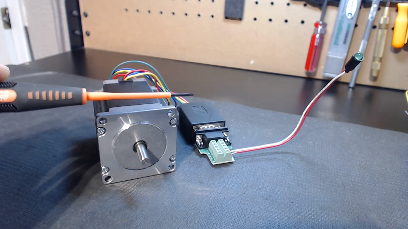
There are a lot of fun projects you can do with stepper motors salvaged from old printers or disk drives. However, it isn’t always clear how to connect to some strange motor with no markings or schematics. [Corvetteguy50] has a video showing his trick for working out the connections easily, and you can see it below.
The basic idea is simple. Using a special jig, he connects an LED across two random pins and spins the motor. If the LED lights, you’ve found a coil. You just don’t know which coil, yet. You can also short two wires and note when you feel resistance when you spin the shaft.
This gets a little trickier with some motor types, for example those that have encoder outputs which won’t do anything to drive the motor. Others have a case ground wire. Steppers have either 4, 5, 6, or 8 drive wires so if you have one more than any of those numbers it is likely a ground wire.
There are other ways to identify the pinout, especially if the motor has 4 or 6 wires. For a 4 wire motor, you can measure resistance until you find a pair that read a relatively low resistance. Then you simply have to guess which one is A and which is B. If you guess wrong, the motor will spin backward, as these are bipolar motors.
For a 6 wire device, the extra two wires are center taps and a 5 wire motor will have both center taps tied together. Measuring resistance between two wires should give you one of three readings. If you read an open circuit, you are on two different coils. If you read a resistance, you can record it and measure some more pairs. The resistance readings will cluster around two different values. The pairs with higher values are the coil ends. The remaining two wires are the center taps and you can tell which is which by which end they are connected to. Of course, in a 5 wire motor you’ll only have one wire left. Those motors can only be used in a unipolar configuration, but a 6 or 8 wire motor can be either.
If you want more information on these kinds of motors, we’ve covered them a lot over the years. Manually controlling one is pretty informative, too. There’s also the classic Jones on Stepper Motors.


This would make for a very interesting and useful flow chart.
Yes, flowchart. I gave up at 3 minutes of waving screwdriver.
Nice one thanks :-)
Of course with modern switching devices, suitable processor, instrumentation (eg current, rotation etc) and some basic algorithmic software procedures should be possible for a single module to work out connections automatically as well as some basic ratings for bulk of small steppers…
“Steppers have either 4, 5, 6, or 8 drive wires so if you have one more than any of those numbers it is likely a ground wire.”
So, if i have a stepper with 5 wires, the 6th wire is the ground ? or is it a 6 wires stepper ? Shall I start counting from left or from right ?
5 wire steppers are unipolar motors with the centre taps connected together.
I have a stepper with 10 wires:5 phases and it does not have magnets. It seems to be of the variable reluctance type, about 12 to 15cm long and 7cm square – and not very strong .
Let’s not forget the 6 wire, three phase stepper motors. Or even the five phase ones.
I want to know more about dc motors with rotary encoders and how to re use them as well
https://hackaday.com/2016/02/13/brushed-dc-servo-drive/
And this beats using an ohmmeter how?
exactly… is this really a hack? We are doomed as a civilization :)
The 5 wire “unipolar” motor can be used as bipolar in fullstep mode using a simple double H bridge (L293 etc). In this mode the center (common wire) will have the same voltage (1/2 Vsupply) and no current runs in the 5. Wire. The benefit is same torque for half the current.