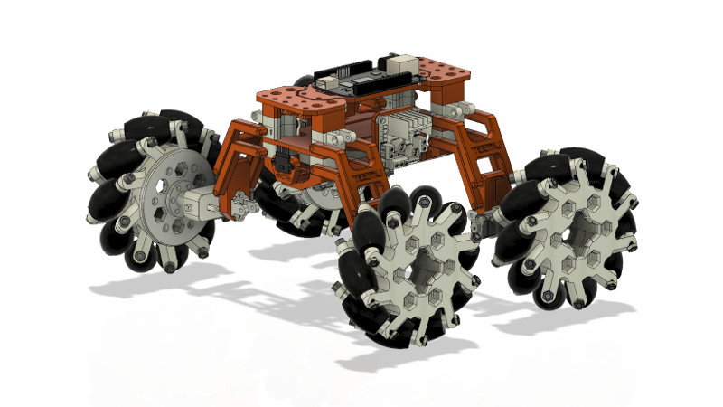
If your interest lies with robotics there are a multitude of different platforms for you to build. [Teemu Laurila] was frustrated with what was on offer, so designed his own with four-wheel double wishbone suspension and mecanum wheels for maximum flexibility.
It’s a design that has been through multiple revisions since its first iteration in 2015, and along the way it’s clear some thought has gone into it. That double wishbone suspension features an angle for a high ground clearance, and is fully sprung. Drive comes from small motor/gearboxes at each axle. The chassis meanwhile has plenty of space for a single-board computer, and has been specifically designed with the BeagleBone Black in mind.
This build isn’t fully DIY, as the mecanum wheels appear to be off-the-shelf items, but the rest of the project makes up for this. If you need to make your own, it’s hardly as though there aren’t any projects from which you can borrow components.


Hey! The mecanum wheels aren’t off-the-shelf parts! They are completely 3d-printable too! The rolls are designed to be printed out of 95A TPU and the rest can be printed from PLA or ABS. I just haven’t published the STL-files because I haven’t tested them yet. The prototype versions (that could in theory work, dunno yet) can be found from the Fusion 360 project I published on my Patreon.
You need more patrons on Patreon. C’mon Hackaday community! Let’s get this guy a few more supporters!
I don’t understand why this robot needs holonomic drive when there only one axis with high ground clearance. Just add steering and use normal wheels.
Why not? With mecanum wheels it’s able to drive sideways and turn around it’s center of mass with ease. Agility is especially handy for a small robot like this. If I were to use steering it would add a large turning radius, more moving parts (keep in mind this is all PLA) and at the same time reduce space from crucial components such as the battery & electronics. And if you don’t like the big clearance, just add something to the bottom (camera, beefier battery, etc.)! :)
The Wheel>Motor>Chassis connection setup doesn’t look very rigid, and would likely be a failure point. I know that the design is done for “maximum flexibility”, but some parts shouldn’t flex. Maybe I’m wrong, but to me it looks ripe for a redesign.
What parts would you change and how? The frame doesn’t flex that much because the shocks are placed in the center of the linkage and the middle of the robot consists of multiple, quite large parts. I haven’t been testing the rigidity that much yet, but I can tell that the gearboxes will snap in half before the 3d-printed parts do.
The project link(s) are broken as of Oct. 2022 and the author/designer doesn’t appear to have an account here anymore. Anybody know what happened to this project ?
The creator’s website seems to be down, so I switched the main link to the project’s Thingiverse page and added the YouTube video.