It is a common situation in electronics to have a control loop, that is some sort of feedback that drives the input to a system such as a motor or a heater based upon a sensor to measure something like position or temperature. You’ll have a set point — whatever you want the sensor to read — and your job is to adjust the driving thing to make the sensor read the set point value. This seems easy, right? It does seem that way, but in realitythere’s a lot of nuance to doing it well and that usually involves at least some part of a PID (proportional, integral, derivative) controller. You can bog down in math trying to understand the PID but [Electronoobs] recent video shows a very simple test setup that clearly demonstrates what’s going on with an Arduino, a motor, a distance sensor, and a ping-pong ball. You can see the video below.
Imagine for a moment heating a tank of water as an example. The simple approach would be to turn on the heater and when the water reaches the setpoint, turn the heater off. The problem there is though that you will probably overshoot the target. The proportional part of a PID controller will only turn the heater fully on when the water is way under the target temperature. As the water gets closer to the right temperature, the controller will turn down the input — in this case using PWM. The closer the sensor reads to the setpoint, the lower the system will turn the heater.
For some applications, this is enough. But what if there are very small errors? Perhaps the set point is 90 degrees and you are 89.8. That won’t correct quickly in a proportional-only control loop because the heater won’t be on very much due to the small error. The integral part of the loop will react to small errors over time, adding a small bit each time the system isn’t in the right state. The derivative part is the opposite. It affects the output in reaction to sudden changes such as an ice cube landing in the tank.
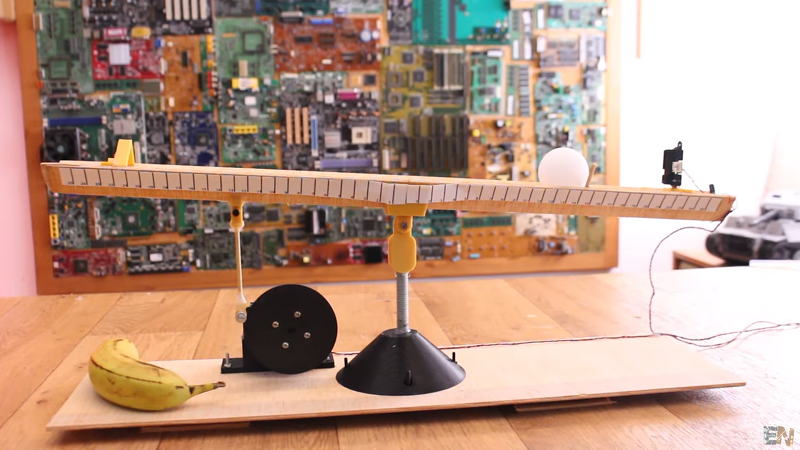
The example rig is a seesaw-like balance beam and uses a lot of 3D printed parts and some plywood. The input driver to the system is an RC servo that can tip the seesaw to a different angle. An IR sensor determines how far the ping-pong ball is from the edge of the beam. With everything wired to the Arduino, you have a pretty good testbed for a controller.
If is common to “tune” a PID by setting Kp, Ki, and Kd constants that determine the “strength” of each action. With the beam, you can watch how tuning affects the system. By setting a constant to zero you can turn off that part of the algorithm, and it is very instructive to see what each part of the equation does to the ping-pong ball.
Even if you have used PID before, you will enjoy seeing this illustrative demo. It would be great in the classroom. If you want to see a temperature example, we’ve seen that done with an Arduino, too. PID is integral — sorry — to flight control systems and self-balancing robots, too.


I saw this video right after it appeared on Youtube. It’s a magnificent demonstration of what each of the three components contributes towards the mix.
Boeing says all that is way too complicated; just keep pointing the airplane nose down and let the pilots handle the results.
In other words: I desperately need to find a purpose for my otherwise useless 3D printer.
No need for jealousy dude, 3D printers are very affordable these days.
Sometimes I print things that could be made in other ways. I do it to improve my design skills. Simple objects used to take me hours to model. Now I can make complex assemblies in a fraction of the time.
This is a copy of https://youtu.be/HRJiow_k-V0 published in 2015 more information at https://roble.uno/control-pid-barra-y-bola-arduino/ (in Spanish)
Yeah, ElectroNoobs copies s**t all the time :D
He copied Dave Jones’ t-shirts, is now making ugly t-shirts with the Arduino logo, copied a tutorial or two from Andreas Spiess…
Who knows how much content he took from Spanish channels and made into english without crediting ;)
That Estudio Roble video is very good, for people who can at least fake their way through a little spanish. (And he seems to have the PID parameters tuned in better to boot!) Too bad it looks like he stopped making videos.
For those who can’t dig spanish, I would say that the Electronoobs vid is a faithful copy. It’s worth a watch.
Too bad about the lack of attribution. One sentence and a link would take away all of the bad taste left in my mouth.
I’m looking at the code for this project and wondering what the purpose of the below is:
if(PID_total 160) {PID_total = 160; }
myservo.write(PID_total+30);
Why cap at 20 for the low end and 160 for the high end? Additionally why is the value of 30 added to the PID output?
Because cheap servo motors tend to not work very well close to the limits.
they start acting jerky pretty quick.
the +30 must be something he factored in because it made it work better.
PID-EN: Proportional, Integral, Derivative: ElectroNoobs
Less cynically, the 20 and 160 (plus 30?) represent the reasonable limits for the servo’s travel. The 30 is strange, and probably doesn’t help him. Try without?
Another trick people often apply is anti-windup, where you limit the maximum value of the “I” term, which can get pretty crazy if the machine sticks for a while.
There’s often some degree of fudging like this in a real-world PID control loop, and it can either represent real physical constraints or make up for poorly chosen parameters, or both.
BTW: to make this a lot more intuitive, I would set the different PID terms by turning potentiometers so that you can tweak them in real time and see the results. That would be a super cool demo…
Electrical engineering students are really going to get a lot of mileage out of this, thanks!