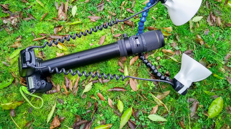
Macro photography — the art of taking pictures of tiny things — can be an expensive pastime. Good lenses aren’t cheap, and greater magnification inflates the price even further. One way to release a bit more performance from your optics comes in the form of an extension tube, which mounts your lens further from the camera to zoom in a little on the image. Back in the day with a film SLR you could make a rough and ready tube with cardboard and tape, but in the age of the digital camera the lens has become as much a computer peripheral as an optical device. [Nicholas Sherlock] has solved this problem by creating a 3D-printed extension tube for his Canon that preserves connections between camera and lens.
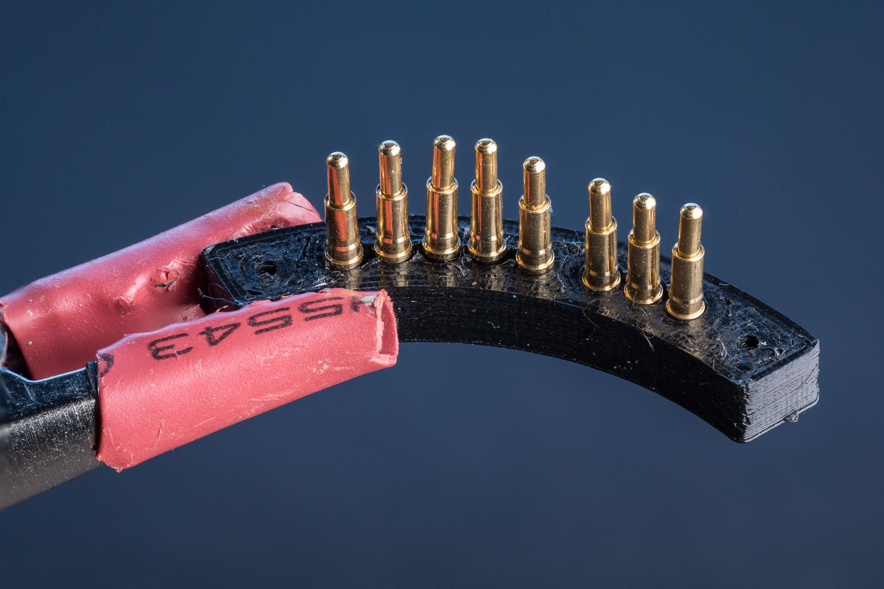 More details of this 300mm monster’s construction go so far beyond a plastic tub formed of two threaded sections with adapter plates at the ends. He’s using off-the-shelf metal rings to fit camera and lens just right, but making the electronic contacts is where it gets interesting. On end uses pogo pins, the other provides a contact block made of nail heads. In both cases the 3D-printed parts are designed to provide mounting points for the pins and nails. The assembly technique is worth a look both because of the design and as an example of how to document all the juicy details we’re constantly looking for in a great hack.
The results speak for themselves, in that the photography provides an impressive level of close-up detail. If you would like to build your own tube, it is available on Thingiverse.
Macro extensions seem far between here, but we’ve brought you a few lens repairs in our time.
[via /r/photography]


Im glad the macro photo of the contacts is nice and sharp
In the reddit post there are some examples of the resulting pictures, like this one: https://imgur.com/a/RhdWomF
Link to said Reddit post please?
Last link in the article
Common wisdom is that to use a conventional lens in an extreme macro configuration like this, you reverse it. An optically-thick complex lens like this is optimized for close focus on one side (the sensor, generally), and far focus on the other (the scene being photographed, usually).
In extreme macro photography like this, you arrange the lens so the optical elements optimized for close focus are facing the object being photographed, i.e., you reverse it. Reversing rings for this purpose are commonly available and fairly cheap. Not using the lens in reversed configuration causes degraded image quality, particularly at the edges of the field. [Nicholas] complained about vignetting: this might be the cause.
A big downside of the reversed approach is that the lens’s rear element, aperture lever and contacts are now exposed and easily damaged. The OP missed a tremendous opportunity here, where he could have reverse-mounted it and then created a ‘floating’ mount on the rear (object-facing side) to permit electronic control of the lens, and protect the rear of the lens at the same time. It would involve running the control wires along the outside of the lens, but that’s not a huge issue.
My impression was that he wanted a long working distance which he, in my understanding, would not get by reversing the lens (rather the opposite).
So you’re saying that the rear element of the lens, designed for a working distance of 40 mm or so, is better working at 300+ mm (the length of the extension tube) than at 170-240 mm that it would work at if used in reverse.
Maybe he’s saying; “if you want to take a macro of a cobra’s eye, you want to be as far from the cobra this device lets you.”
B^)
You can get devices as you describe for connecting contacts on reversed lenses ready-made on ebay.
Once, I made a (big) ring to adapt nearly any lens reversed on a Nikon 2,8/300, it’s an expensive extension tube, but it has also other purposes : http://www.cuk.ch/articles/5350/, you can see the first results here : http://www.cuk.ch/articles/5069/ and there : http://www.cuk.ch/articles/5674/ (all in french).
The smaller the front lens, the bigger is reproduction ratio, the longer the back (camera side) lens, the bigger reproduction ratio also, but for really sharp images, I had my best results with a Leica M 1,4/50 reversed on the 300,
it gives an enlargement of 6:1, with more wide angle, the enlargement is more important, but I get sharpness issues due to motion, like slow speed blur, even at high speeds : it looks good when I focus, but the pictures are not as good…
My similar attempt, but I was lame and just purchased a reverse adapter ring to do it: https://flic.kr/p/dvhoxA
This rig is only around 1:1, and standoff distance only 45 mm. As you say: shorter front lens gives higher magnification: If I replace that monster 85/1.4 with a 28 mm it becomes 5:1, with a similar standoff distance. With my 28mm the pictures are nothing to write home about, but the 1:1 images with that Rokinon front end are very satisfactory: great for digitizing negatives (much better than my negative scanner).
(a dupe/repost of a previous image-embed attempt, but I didn’t seem to cast the correct incantation and it didn’t appear).
oh… my… god… YES YES YES!!!!
Someone with more mechanical skill than I did figured out how to DIY manufacture an EF pogo connector.
YEEEEEEESSSS!!!!
This solves a major blocker for a project idea I’ve had for a LONG time.
(side note – lots of people, including many manufacturers of commercial photographic accessories, seem to have problems making the body side of the EF mount. On a regular basis you find EF-to-E adapters with EF-side pogos prone to jamming in a retracted position.)
Yup, that’s pretty neat. I’ve got a half-completed extension tube waiting for this.
As for why I’m making my own extension tube, I wanted a shorter one than the 13mm minimum which everyone sells. Sometime you don’t want to go too small!
In my case – I’ve been reverse engineering Sony’s E mount protocols on and off for a while – https://www.dyxum.com/dforum/emount-electronic-protocol-reverse-engineering_topic119522.html
My eventual goal (if I ever get there… too many other projects!) is an open-source EF-to-E adapter.
Figuring out the mechanical side of the EF pogo pins was a major head-scratcher for me. As I’ve said, I’m mechanically inept. (maybe less so than the average person, but I work at a company with lots of MechEs who have amazing skills.)
Just buy an old film eos camera and use that mount. They are really cheap. Especially without lens
Not suitable when you’re thickness-constrained (such as a mount adapter) and when you’re trying to come up with a potential open source design for others to implement.
Cannibalizing Chinesium extension tubes readily available on Amazon is one thing. (The Kenkos this project uses are very expensive, but you can likely get the metal mount flange hardware from far cheaper extension tubes) Cannibalizing old used cameras is another.
For a thickness-limited situation, note that the “0932” solder-tail pogo pin I’m using is 7.67mm from plunger tip to solid base, then the solder tail extends a further 4.3mm below that. You could trim off the solder tail and solder to the side of the pin instead.
In my design the plunger protrudes 1.67mm above the top of the mount surface. (So a max-stroke of 1.6mm or higher is a good idea, which seems to only include Mill-Max’s “long stroke” range). You might be able to get away with a 1.4mm standard-stroke part since they don’t get crushed flat with the mount surface in normal operation.
The inter-pin spacing on the EF mount is 2.257mm (5.75 degrees on a circle of radius of 45mm, as near as I can figure it), and this a constraint in choosing a pogo-pin – the pin’s maximum diameter has to be smaller than this so that neighbouring pins don’t short out against each other. (And when 3D-printing with a 0.4mm nozzle it’s ideal if the max diameter is smaller than 1.857mm so you can get one perimeter between pins). The 0932’s max diameter is 1.83mm which is perfect.
The 0930 looks like the pick of the standard-stroke (1.4mm) pins, with height 4.42mm after the solder tail is removed.
Whoops I meant “diameter of 45mm”, not “radius of 45mm”.
If you have a 200mm lens you can just stick microscope objectives that are designed for a 200mm tube length on the end of the lens. They make adapters to fit both the mitutoyo and Nikon standard objective threads. Then you can do stuff like this without having a 2 foot long lens.
At what working distance? This approach achieves 170mm working distance at 5x magnification.
Nicholas: is that 170 mm figure really the distance between the front element and the object when operating at 5:1?
Because if so, Sigma is doing something kinda magical in that lens: The lens equation arithmetic requires that increasing the ratio from 1:1 to 5:1 in a 180mm lens must necessarily reduce the working distance by 144mm.
Since at the ‘normal’ 1:1 macro that lens has a working distance (front element to object) of about 200 mm, this means at 5:1 the working distance must reduce to about 56 mm between the front element and the object.
If you’re really getting 5:1 at 170 mm from the front of the lens, I’d be very, very interested in how Sigma manages to accomplish that.
Yep, 170mm! You made me doubt myself so I rechecked it, here’s some pics of the measurement:
https://imgur.com/a/sHFSS6V
Note that my tube ended up being around 330mm long in total due to a miscalculation during modelling. Forgive the image quality, my cellphone is godawful.
Could this discrepancy be explained by the Sigma’s focal length not being 180mm at closest-focus?
Impressive. It’s clearly a telephoto configuration, but there must also be a varifocal adjustment going on too. It would be interesting to find out where the actual entrance pupil is situated. I would not be surprised if it’s outside the physical lens body.
Why using 3d printing??? Professional are building this type of extension very easily and fast since years. Probably with 3D printing is much slower