These days, it’s common among us hackers to load a stepper motor with forces in-line with their shaft–especially when we couple them to leadscrews or worm gears. Unfortunately, steppers aren’t really intended for this sort of loading, and doing so with high forces can destroy the motor. Fear not, though. If you find yourself in this situation, [Voind Robot] has the solution for you with a dead-simple-yet-dead-effective upgrade to get your steppers tackling axial loads without issue.
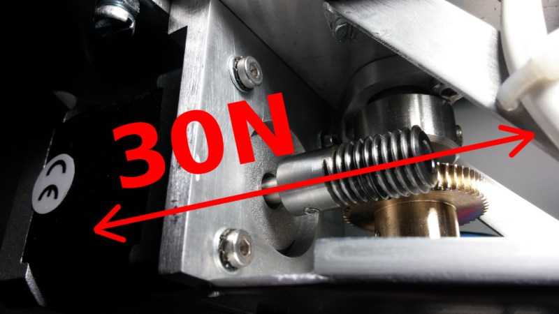
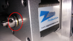
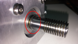
In [Voind Robot’s] case, they started with a worm-gear-drive on a robot arm. In their circumstances, moving the arm could put tremendous axial loads onto the stepper shaft through the worm–as much as 30 Newtons. Such loads could easily destroy the internal stepper motor bearings in a short time, so they opted for some double-sided reinforcement. To alleviate the problem, the introduced two thrust bearings, one on either side of the shaft. These thrust bearings do the work of redirecting the force off the shaft and directly onto the motor casing, a much more rigid place to apply such loads.
This trick is dead simple, and it’s actually over five years old. Nevertheless, it’s still incredibly relevant today for any 3D printer builder who’s considering coupling a leadscrew to a stepper motor for their Z-axis. There, a single thrust bearing could take out any axial play and lead to an overall rigid build. We love simple machine-design nuggets of wisdom like these. If you’re looking for more printer-design tricks, look no further than [Moritz’s] Workhorse Printer article.


Yes a few years ago I built an i3 variant printer called the i2 Samuel. It’s design had thrust bearings on the z to eliminate stress on the stepper
Is the link broken for anyone else?
Most steppers have allowable axial load no more than it’s mass*g. If it’s more, your design is flawed or amateur, which is often the first.
Good method. Incidentally can anyone tell me where to get small bearings? I hacve a fair few mains fans that have the rumble of doom ™ but otherwise work.
McMaster Carr is a good place.
“This trick is dead simple, and it’s actually over five years old.” Yes, I would agree that thrust bearings were invented more than five years ago.
+1
Stepper motors seem to typically have a degree of axial float in the shaft, taken up with a spring washer.
This is to keep the axial load on the bearings within specification as the motor heats up and differential thermal expansion takes place.
The arrangement shown here does not have provision for thermal expansion, so there might still be longer term problems with the motor bearings. Whether there is or not will depend on where the shaft sits with the thrust bearings fitted.
Ideally the thrust arrangement would be all at one end, with the other end free to float as parts expand.
It might actually be better to have a thrust bearing only at the output end, as close as possible to the output bearing and to rely on the original output bearing for thrust control in the out-of-the-motor direction.
Assuming (for the sake of argument) a 604 bearing with a 4mm shaft (rather than the 6mm shaft of a Nema23) then the ratiad radial load is 360N and the rated axial load is 0.25x this (it is 0.5x for larger bearings). So the original deep-groove ball on the output end should be OK with an axial load of 90N. In the example given (30N) there does not actually seem to be an cause for concern as far as bearing life goes. However the axial float in the shaft against the preload spring probably does need to be addressed, and a single thrust bearing on the output end would do that.
Better, though, would be to have a separate set of thrust bearings for the worm, and to allow the whole motor to float axially with a suitable torque-reaction arrangement. This is what you would have with the common arrangement of a motor driving a ballscrew with its own set of angular-contact bearings through a Lovejoy or similar coupling. This does add a lot of extra length, however.
Andy, I was going to write the same thing: He seems to have added bearings without any play and just hopes that the right bearing will take the load.
That last paragraph exactly. Unless built with tapered roller or angular contact ball bearings, or separate thrust bearings, a motor should not have large axial loads put on its shaft.
Motors should drive shafts through belts, gears, flexible couplings or through a splined coupler. The more rigid the coupling, the more accuracy is required in the motor to shaft alignment.
Why not a tapered roller bearing?
Agreed, the arrangement chosen here is possibly even detrimental to the lifetime of the motor. There is a good chance the ball bearings of the motor itself are still getting significant load. The photo seems to show enough room for an end support on the worm. Choosing to support the worm with 2 angular contact bearings on either end, and driving it through a splined or keyed shaft would be a better option already imho. A flexible coupling in between is a further improvement above that.
ime steppers doesn’t really take any axial load until you bottom out the spring washer, the shaft is a slip fit in the bearings
Depends on the stepper. I’ve also seen them with one or even both of the bearings taking axial loads if the spring washer gets compressed too far.
so like I said, as long as you don’t bottom out the spring washer there is no excessive axial load on the bearing
@Fonz,
Yes, but those spring washers are usually very weak, so you WILL bottom them out easily in an application like this.
@ThisGuy that’s the point of the thrust bearings they lock the rotor in it’s center position so the spring washer never gets into play
I know everything’s relative but I can’t help finding the hyperbole here a bit amusing – in more conventional units, “tremendous axial loads of more than six pounds”
This is a poor choice. Roller bearings work well because they reduce friction by rolling instead of dragging- the inherent problem with needle thrust bearings, is that the end of the needle on the o/d is travelling faster than the i/d (unless the needle elements are tapered, which for most applications nobody factors in). There are of course tapered needle thrust bearings, but this dude would have been better off using spherical thrust bearings instead- he would have essentially no limit on his axial load until either the bearings fractured or the washers brinelled, either or which would be way past 6lbs.
Also, with proper pretension set on a spherical thrust bearing, he’d have almost no radial resistance. Good idea, could have used some specialist input.
Nm my babbling, i was under the impression that he used straight needle bearings, but those centre races dont look the part
Liking the discussion of all the different bearing configurations and setups, would love an article series covering stuff like tapered roller and tapered thrust bearings in practical design examples. making me think about a lathe I’m designing.
From just the pic, if at all possible I would put a support out at the end of that shaft off the stepper, most of the wear and side loading forces could be better dealt with by support at the place of maximum side deflection out there.
Agreed with the comments about tapered roller bearings, lathe spindles use them in preloaded pairs at the front because they are designed to take axial and lateral loads simultaneously, as would be generated by a worm gear here.
Could they decouple the stepper motor shaft from the shaft driving the worm gear with something like a servo-flex coupler, spider coupler, or plum coupler? Not sure of the torsional load they are working with. Or perhaps a 1:1 gear?
Then they could direct the force into the motor mount frame with almost no force into the stepper shaft.
Your supposed to use a bearing capable of accepting the expected thrust load (angular contact, taper, thrust etc), with ball or acme screws anyway. The motor’s bearings are usually not meant to handle such loads, and not supporting the screw properly will negatively affect accuracy. Ideally, the screw positioning assembly is 100% self supported without the motor attached, and the motor only supplies the torque. That’s machine design 101. It may be possible, if the load is within spec, to forego the thrust bearings but it is generally bad practice to do so because thrust loads may cause misalignment of motor internals which will affect performance. Just look up any normal ball bearing, and take a look at the acceptable thrust loads and you might actually be surprised to find how small the rated thrust loads are in most cases.
Since no edit button, i add also, that in most cases, depending on your desired level of precision, a worm gear for all intents and purposes can be treated like a ball or acme screw, as the forces are pretty much in the same directions.
The load on a worm gear is significantly different from that on an Acme or ball screw. Since Acme and ball screws are used with full nuts, the load is almost purely axial. Worms act against a gear on one side only, so there is also a radial load.
I would go the other way, many would be surprised to find how _large_ the axial load capacity of a ball bearing is. At least 25 of the radial load, and 50% on heavier section / larger bearings.
By all means, if you don’t mind severely reduce bearing life and possible catastrophic failure, go ahead and rely on a standard ball bearing to handle a thrust load! FWIW, The reduction in contact area that occurs when a standard ball bearing is in thrust load is pretty marked. If the bearings are sufficiently over sized, you might not see anything severe or dangerous, but that is not typical, especially if you got your parts ‘on the cheap’.
Now you’re just being contrary. If a bearing’s manufacturer says it’s good for x Newtons of radial load, that’s the spec.
I based my numbers on the SKF online guides. It is possible that they know their bearings better than you do.
If you prefer random anecdotal arguments: Motorcycle wheel bearings are a pair if deep-groove balls, They see forces in all directions almost randomly, and last for ages. At least 120,000 miles in my testing.
But a deep Grrove bearing is NOT a standard ball bearing.
But you have missed one crucial point: a Deep Groove Bearing is NOT a standard ball bearing.
The default “ball bearing” is the deep groove ball. If it isn’t something else it’s a deep groove ball. See the categories here. https://simplybearings.co.uk/shop/Products-All-Bearings/c4747_4514/index.html