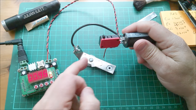
[Julian] needed to weld a bit of nickel to some steel and decided to use a spot welding technique. Of course he didn’t have a spot welder sitting around. Since these are fairly simple machines so [Julian] set out to build a spot welder using a charged supercapacitor. The fundamentals all seem to be there — the supercap is a 100 Farad unit and with a charge of 2.6V, that works out to over 300 joules — yet it simply doesn’t work.
The problem is in how the discharge energy is being directed. Just using the capacitor would cause the charge to flow out as a spark when you got near the point to discharge. To combat this, [Julian] put a microswitch between the capacitor and the copper point he expected to use as the welding tip. The microswitch, of course, is probably not the best for carrying a large surge of current, so we suspect that may be part of why he didn’t get great results.
The other thing we noticed is that he used a single point and used the workpiece as a ground return. Most spot welders use two points near each other or on each side of the workpiece. The current from the capacitor is probably just absorbed by the relatively large piece of metal.
The second video below from [American Tech] shows a 500F capacitor doing spot welding with little more than two wires and it seems to work. Hackaday’s own [Sean Boyce] even made one out of some whopping 3000F caps. It did work, although he’s been pursuing improvements.


He could’ve TIG welded it @ about 2-3 amps.
If his TIG skills are as awesomely bad as mine – then he’d just set everything on fire and make a huge mess. I prefer spot welding. Have generally used electrolytic caps. Car battery with a bit of wire in circuit as a fuse works well too.
There are a number of things going wrong here: switch contact resistance, insufficient contact pressure, heat sinking by the large piece, possibly inductance in the current loop.
I will hazard a guess that it is not ” The current from the capacitor is probably just absorbed by the relatively large piece of metal.”
Think about the actual current flow between two electrodes and the density of charge carriers in that region. Now think about the current flow between the clip lead and the single point electrode. Hmm….
One doesn’t simply absorb current…
Resistance is futile? :)
A recent star trek Borg acquisition not quite fully trained yet but, returning to primal habits:-
“You cannot escape, Procreation is Fertile”
With those nickel strips, wouldnt it be helpful to press stress a pair of small dimples facing down where it’s going to contact onto the final material, such that a pair of close capacitor prongs get some positioning aid and only pass current through the nickel with none on the base metal. Of course this would need some sizable pressure and better than passing any current through a battery when attaching strips to either end ?
Thanks for post :-)
Yeah, in physics and english, words have meaning. Current is not absorbed. Current flows through something. As much that enters it exits it. One substance have 10 amps flowing though it absorbing 1 watt of energy, and another substance can have 10 amps flowing through it while absorbing 100 watts. Amps are not absorbed or consumed, power is. Too many people conflate power current and energy.
Haha, many people conflate current power and energy. I just did. “Absorbing 1 watt of energy”. Uggg.
Yes, there is a common misunderstanding in the Automotive Resistance Welding World that the KVA rating of the welder has something to do with how much current a welder will produce. The current is actually transformer output Voltage divided by the impedance of the secondary circuit.
And with these high currents, the nameplate Voltage can’t be used for this calculation, because many Volts are dropped within the secondary winding. So the actual terminal voltage is not simply figured out by the turns ratio, it has to be observed under load..
Your comment about “Absorbing 1 Watt of energy” is fine with me, because I think of that 1 Watt as heat, and sure it will “absorb” it and its temperature goes up. No complaint here…
Say I provide 100 watts to a water heater, how hot is it? Well it depends on several things, thermal properties of water and the container aside, time is arguably the most important, how long do I supply it 100 watts. You see, watt is an instantaneous value with no dimension of time. 100 watts for 0 zero hours is zero energy, while a 100 watts for an hour is a unit of energy, specifically 360,000 joules.
What ?
A Watt is defined as a Joule of energy delivered over the (average) period of a second, it has dimensions of time.
It is accurate and more appropriate to state a Joule has no units of time only of energy, you can then decide how it’s applied over what period and for convenience and convention average this to period of a second ie a Watt for most purposes.
Interestingly your calculation of the total amount of energy delivered over the period of an hour is correct but, to get that you Must accept first that the Watt has units of time (seconds in this case) as an hour is 3600 seconds so the time units cancels out in that multiplication. W=J/s if at least for the sake of how units are dealt with across all science disciplines…
Current in amps = volts / ohms
Power in watts = volts × amps
Energy in joules = watts × seconds
Joules has a dimention of time, not watts.
w=j/s because j=w×s which means w=w×s/s and reduces to w=w with no dimention of time.
What you want is a few photoflash capacitors or a large electrolytic from an amplifier, even a few of the mylar film block style ones can discharge pretty fast. I was experimenting with a pen style mini spot welder with wireless charging rather than having it continuously powered.
If you look up the ESR of single typical 100F supercap – it’s really borderline too high for a decent spot weld. If you parallel two or three you’d be in pretty good shape if the electrodes were soldered to the supercap leads. I think a mechanical switch is not a possibility – but a super low on resistance FET may be OK – you’d like one with a milli-ohm or less at several hundred Amps. I say FET because a parallel supercap bank is 2.7v max, so you would waste a lot of energy in an SCR or other switch.
Most supercapacitors have significant internal resistance and inductance. They store a lot of energy in there, but their limitation is that you can only recover it at a certain rate.
As CRJEEA says, photoflash capacitors, in fact, any conventional electrolytic cap, is a better bet for creating a current surge, albiet it at the cost of higher voltage to store an equivalent amount of energy.
A low-voltage alternative would be a parallel array of conventional low-esr elyctrolytics
Yep, the capacitive discharge welders I have worked on are very simple, line doubling voltage regulator charges up a couple big electrolytics in parallel and a big hockey puck scr discharges it. High voltage is nice because it can burn though coatings. You can also dump that high voltage though a transformer to get a low voltage, high current pulse. Lots of easy options.
Discharge bank of capacitors through a ferrite core transformer with secondary winding being made of single loop of copper tape 1-2mm thick. Convert for example 10A at 100V to 10kA at 0,1V…
It might be useful to actually know, how much energy one needs to have for spot welding, and start from there. 4-10kJ should be enough for most situations. Welding process takes only few milliseconds…
Excuse the ignorance but “Tape” and “1-2 mm thick” don’t add up, that sounds like dead soft sheet metal that just so happens to have an adhesive back.
It’s the problem of translation. By “tape” I meant a strip of copper 1-2mm thick. Usually they are 5-20mm wide. Usually used as high-current conductors for spot welders, inverter type welders and such…
Consider the ESR (Equivalent Series Resistance) of the capacitor. Supercapacitors tend to have a notoriously high ESR, such that the current is dumped relatively slowly. Plus, even if you can dump the current rapidly, the internal contacts of the capacitor may fuse, destroying the capacitor (The internal structure typically consists of very thin Aluminum foil, and it doesn’t take much to cause it to fuse (go POOF).).
You’d be better off using a photo-flash rated capacitor, since these are designed to dump their entire energy in a very short period of time.
First clue: It doesn’t weld the switch contacts closed. Second: Electrodes are very small compared to welders, which doesn’t really matter because other parts of circuit are too light. Moral is, start small and work up. Maybe aluminum foil then shim stock a couple thou thick. A cheap set of automotive feeler gauges are a great source of bits of steel of many thicknesses. https://www.amazon.com/Hotop-Blades-Feeler-Imperial-Measuring/dp/B06XHXJG31/ref=sr_1_3?crid=2RTNSV5CHL5OO&keywords=feeler+guages+set&qid=1565901008&s=gateway&sprefix=feeler+gu%2Caps%2C207&sr=8-3 and an assortment of brass shim stock is mighty handy.
Ive successfully spot weleded with 2x 450v 350uf in parallel. Its very easy and super deadly.
Supercap iss too much farads at too low a voltage. Resistance of the too skinny wires would be way too high.
Also the microswitch should probably explode and is not required. There is no way it can handle the discharge. You wont get an arc before contact, even at 400v. Well maybe a really short one, but you need 1kv to arc 1mm. Even with 1mm arc, probably still works. Arc heat might be a bonus.
Yes the transformer approach works as long as it has sufficient pulse handling capacity.
Incidentally I once tried this with an audio capacitor of the 1F type, it worked but not well.
Perhaps as others have pointed out ESR is a bigger problem so 2*0.5 in parallel are better
than 1*1.0 and always use load sharing shunts or resistor + Schottky array so one capacitor does not hog all the current.
Hmm, regardless of whether this is a case of “clueless idiot fails to make spot welder”, or “play the fool and get lots of views”, it certainly does provide insight into the state of the collective conscience IMO.
That’s a bit harsh… it’s not everyone who has an intrinsic and encyclopaedic knowledge of everything going on in all electrical circuits like your good self. Some people have to learn through experimentation and practical experience.
Julian does a lot of good for helping new hobbyists into the field, and he’s helping people do it on a tight budget too.
I may be wrong here, so educate me, not conflagrate me – Aren’t old school, giant clamp style spot welders used in sheet metal work just more or less low voltage / high current transformers that use the relatively small points of their electrodes to provide a bit of resistance along with the small, focused cross section of the workpiece? That massive current has low impedance until it sees the small surface area of the electrodes contact with the work piece – effectively a resistor, and ohms law says that P=I^2*R and that P is going to get dissipated as heat; which then fuses the parts?
I myself have a pretty fancy TIG machine at home that can get down to a couple of amps and has pulsed modes, but I’ve not tried spot welding anything with it. I’d imagine I’d want to grind a nice fine point, get the electrode as close as possible to the work so the HF start doesn’t go berserk and one shot with a short pulse? Or if I’m really in the mood for grinding electrodes, turn the HF off and do the same thing, but with contact with the workpiece.
But with this contraption here we have two electrodes, low voltage and high capacitance, and as others have already said, in the case of supercaps, a lot of ESR which is going to limit the current seen in the workpiece – and since it is a cap, the energy stored is still going to be short lived – and the short / low impulse is not going to be enough to fuse anything given all the added resistance in the system.
And as others have as well, you could add more capacitance, maybe even go with higher voltage, lower ESR electrolytic caps, lose the lossey switch, focus the energy to a smaller point with pointy electrodes on both sides of the work, and probably weld something with no problem.
Often it seems these “fails” are all kind of typical – choosing the wrong part for the job. Intentions are well placed, they just didn’t quite understand (or ignored) all the specs in the datasheet. Like trying to use a FET to pass a massive amount of constant current without understanding that you are likely going to need a big heatsink, regardless of the current rating of the device, and it may take way more than 3.3V of gate drive to get the thing to fully turn on or off unless you know what part to buy or get lucky.
The good thing about these failures is that they are almost always an entry point to learning.
> Just using the capacitor would cause the charge to flow out as a spark when you got near the point to discharge.
That might happen with high voltages, but not with low voltages. Just be assertive in making the connection.
> The current from the capacitor is probably just absorbed by the relatively large piece of metal.
No current is never absorbed. Current flows. But once you make current flow through a loop, the power produced is proportional to the resistance encountered. And you need a certain amount of joules in the junction for it to “weld”.
I get that HaD writers are not all experts in electronics or physics, but a lot of people get confused by arc physics. I work on high voltage systems for a living, so there is a lot of cringe worthy stuff I read on here too. An arc is actually more of a current driven event. Where higher voltages come in is that they can cause breakdown when coronal or glow discharge ionizes the gases surrounding electrodes and creates a low impedance path for current to flow (actually such low impedance that current is only limited by the current source feeding an arc), current sustains the arc while the voltage tends to drop off, its a common arc detection / crowbar tactic to watch for increasing current and dropping voltage… Stick welding with a scratch start is a good example: the voltage generated by the arc welder is actually pretty low, it takes scratching the electrode across the work to get current flowing and to start the arc. HF starts on TIG welders start an arc by applying a high voltage to the electrode to induce electrical breakdown so the current can establish the arc and thermionic emissions sustain it. But yeah, for sure 2.5 volts isn’t going to cause breakdown and start an arc without physical contact of the electrodes. But I believe true spot welding is all about the resistance to current and the heat generated fusing the materials and not so much the heat of plasma in an arc, like in the various forms of arc welding.
Welding thin metal is very difficult, as the heat required to reach fusion temperature is absorbed by the electrodes on either sides of the work. If we get much lower than .8mm thickness the current required is higher than thicker sheets.
Another consideration is that the spot weld should be stronger than the sheet metal for a good mechanical connection. So there is a minimum diameter required, based on the thinnest of the two sheets. Generally this is at least 3.5 to 4mm diameter, for metals of .8mm and this diameter requirement goes up for thicker metal, such as 7mm diameter for 3mm metal.
This means we will need a lot of current to make a structural weld, as a little pin-point weld will not be stronger than the metal it is holding together. This is why we use these big machines for industrial welding. We like to maintain 100,000 Amps per square inch of area.
Another point, mentioned by others in this article, is the “absorption of current by the big base metal” I understand the point, it is that all the heat is absorbed by that big base piece. Further, the current that is concentrated in a small area, the size of the desired spot weld, will be dissipated by that thicker sheet. Best practice is to use two tips with the same diameter contact size, and two sheets that are within a 2:1 ratio on thickness.
Capacitor Discharge welding is a higher performance method of spot welding, but the present equipment is much more expensive, and I suspect the low ESR requirement is one of the factors.
well:
j = w x s because w = j/s, which means j = j/sxs and reduces to j=j with no dimension of time.
Many moons ago, I had to design a tester for multilayer ceramic caps that rapidly charged and discharged a single part and captured the discharge scope trace. The discharge was to be as close to a short as possible so the fixture was designed for minimum resistance and inductance. The initial device under test was a 1uf 50v part. A part charged to 50v would yield a nice scope trace of ~100A peak exactly one time. It was not a huge number of joules but enough to pop the brand new $300 Motorola power FET, PROMINENTLY advertised as a 100A transistor, used as the electronic switch. Their app engineer said it had ZERO Imax high current manufacturing margin. You can pull some impressive current from ceramic caps with the right design. The rub is welding needs a lot of joules.