Planning a game of Hacker Jeopardy at your next meetup? You’re going to want some proper buzzers to complete the experience, but why buy when you can build? [Flute Systems] has released an open source DIY game buzzer system based on the Arduino that will help instantly elevate your game. Certainly beats just yelling across the room.
The design has been made to be as easily replicable as possible: as long as you’ve got access to a 3D printer to run off the enclosures for the buzzers and base station, you’ll be able to follow along no problem. The rest of the project consists of modular components put together with jumper wires and scraps of perfboard. Granted it might not be the most elegant solution, but there’s something to be said for projects that beginners and old salts alike can complete.
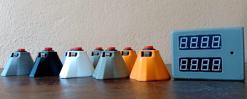
 Each buzzer consists of an Arduino Pro Mini 3.3 V, a nRF24L01, and of course a big pushbutton on the top. Each one is powered by a 110 mAh 3.7 V LiPo battery, though [Flute Systems] notes that the current version of the buzzer can’t actually recharge it. You’ll need to pull the pack out and charge it manually once and awhile. Thankfully, the printed enclosure features a very clever twist-lock mechanism which makes it easy to open anytime you need to poke at the internals.
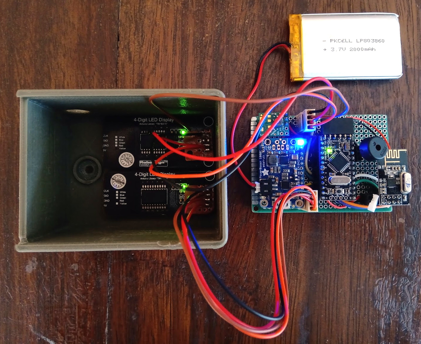
The base station uses the 5 V version of the Pro Mini, with a Adafruit PowerBoost 1000C to step up the voltage from its 2,000 mAh battery. Of course it also has a nRF24L01, and also adds a buzzer and twin four digit seven-segment LED displays. [Flute Systems] says you can expect about five hours of runtime for the base station.
An especially nice feature of this setup is that the eight digit display allows the base station to show the number of each button in the order it was received. So rather than just getting a display of who buzzed in first, you can see the chronological order in which all eight buttons were pressed. Coming up with clever applications for this capability is left as an exercise for the reader.
Of course, there’s more than one way to build a buzzer. If you don’t like the way [Flute Systems] did it, then check out this version that uses 900 MHz radios and an OLED to show the results.


This really needs bigger buttons: http://www.arcadeshop.de/Illum-Buttons-Jumbo-Dome-Button-98-mm-red_505.html
Thank You. Point and link noted.
It’s similar system but via Wlan with an ESP8266, so you can link the result to the game.
https://www.youtube.com/watch?v=1Owd9qIl-tg
Thank You. So nice of you. Let me see if can get the German translated.
I fear these will start moving by themselves, saying “Exterminate!” repeatedly.
You weren’t the only one.
B^)
The pcb antenna of the nRF24L01 module showing though the front was a nice touch.
Yes, but why would you do that? So user can stick his finger on the RF tuned circuit?
Add a LED for click/battery/power confirmation, this gives the user an useful feedback.
Nice project, but with this battery, such system should last 100hours, not few.
System has lots of testing and optimizations pending. Thank You for the info, appreciate it.
Oh, please, stop doing this:
“The base station uses the 5 V version of the Pro Mini, with a Adafruit PowerBoost 1000C to step up the voltage from its 2,000 mAh battery. ”
Throw away the “arduino” thing and simply us an AVR uC. for your hardware.
It runs directly from any battery voltage from between around 2V and 5.5V which will significantly improve battery life without all those silly extra voltage regulators.
ATMEGA328 is also available in a breadboard friendly dip version, and if you want to stay compatible with the “arduino” framework, you only need a 16MHz crystal.
(Which is another silly limitation of the arduino framework, if it was a decent framework, then you could symply #define F_CPU)
It’s open source. Build a version that does exactly that, document how you did it, educate the world a little bit.
However, for the me, prototyping using prototyping tools that I know (and can easily find examples of) is far more productive than hunting down the correct capacitors and resistors need to run the raw chips.
Will using the internal oscillator at 8 MHz reduce the capability to register near – simultaneous presses?
I doubt anyone can be that simultaneous, a very good reaction time for button pressing is 200 – 300ms which should leave enough resolution even with a uC running on internal clock with different voltages from the batteries.
As of now the setup displays the sequence for upto 4 buzzers being pressed together but any more than 4 results in the 5th unit onwards getting ignored.
Gotta have extra voltage regulators, like you gotta have 555’s and other extra jellybean components in your design. It’s the hipster way of electronics. Minimalistic design is greybeard 80’s thing and who wants that? No one.
This is just too simple.
We need a buzzer “framework”.
The button can be connected to an Arduino, that sends a signal to a raspberry pi, that formats the message to MQQT, that sends it to the broker, and a backend, running on as something as simple as a quad-core i7, can process the message, determine which one was first, send a signal to the raspberry pi in each button, which sends a signal to the arudno, to light up the response buzzer.
latency would be just a few seconds!
tl;dr; no frameworks, no arudinos, no raspberry pi’s , no internet connectivity required. FAIL
Unintentionally removed ‘Custom PCB’ under ‘things yet to be implemented’ while editing the blog yesterday.
The system is still undergoing trials and testing.
How does the system resolve simultaneous transmissions/collisions?
I don’t see any time synchronization among them, no carrier sense, no collision detection, no fallback/retry, no message acknowledgement. The message looks like it contains no time stamp, just an ID.
Does it depend on the radio module itself doing code division multiplexing or something?
As far as I know, what is working well as of now is due to the great RF24 library. I’m not that well versed in the concepts you mentioned. Hope to learn more as I delve deeper.
Will be using an STM32 @ 72 MHz and see what difference that makes.
Hello Flute Systems!
I would like to repurpose similar button / buzzer for a different purpose. can I get your contact so I can discuss with you?
Thank you,
Tushar Bhavsar