How do you know if your 3D printer bed is levelled? Oh, don’t worry – you’ll know. Without a level bed, filament won’t stick properly to the build surface and you’ll run into all sorts of other problems. Knowing how tricky it can be to get the bed just right, [Antzy] built a tool to help.
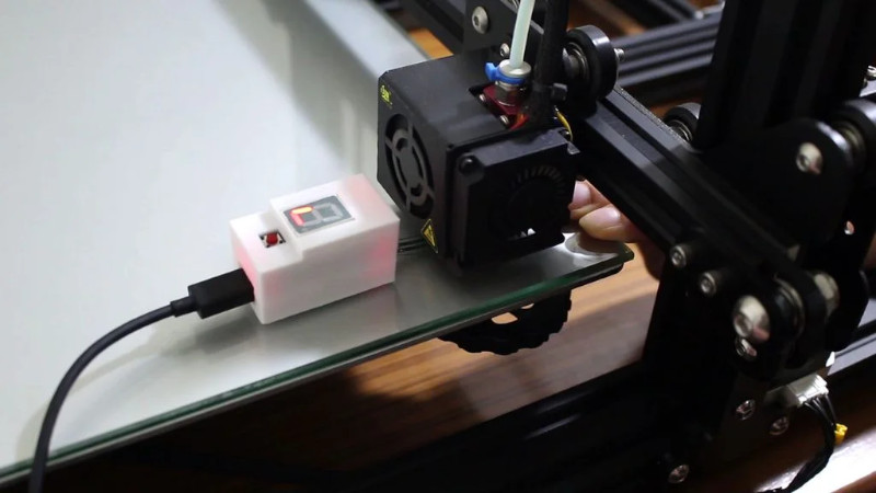
The device, which he calls the FS-Touch, is based around an Arduino Pro Micro fitted with a force sensitive resistor. This allows the distance between the bed and nozzle to be measured based on the force read by the resistor when placed in between the two.
Using the tool is simple. First, the bed is brought roughly into alignment using the typical paper method. Then, a reading is taken from one corner of the bed, and the measurement saved for reference. The other corners can then be set to the same level, with the aid of LEDs to guide the user in which direction to turn the adjustment knobs.
Measuring force in this way has the potential of being more repeatable than the somewhat difficult paper method. It promises to ease the task for users that may be struggling to get their bed in proper shape. Of course, automated bed levelling makes things even easier again. Video after the break.


voron has been using this for about 2 years now …
I’ve been wondering if the same could be done by putting a kitchen scale under the heated bed. Could be connected to the automatic leveling algorithms that are in most controllers nowadays.
Mount one of the force sensor discs to the head, perhaps a servo that can slide it in a groove like a tounge, add a geared motor on each leveling wheel and it can set itself up.
You don’t need to adjust the leveling wheels. The firmware can compensate for any misalignment by moving the z-axis up an down. BTW that’s what Prusa’s i3 is doing since several years.
Correct, but also the Prusa calibration routine actually employs the skew correction that’s been in Marlin for ages.
They use the high accuracy of the PCB lithography for the heated bed to create calibration targets which are “scanned” by the PINDA, this does the 2D XY skew correction which was very important on poorly assembled MK2 threaded rod Y carriages.
These days with the MK3 3030 frame it’s less critical but it’s very nice that’s its there to confirm your machine is built square.
THE “mesh bed level” Z correction happens by probing for offsets before print, which is why you can’t print on a Prusa without performing pre-flight to set the nozzle to sensor offset.
Are these pressure sensitive resistors repeatable over longer periods of time? Feels to me like the polymer foil will get worn out while slightly shifting the sensitivity…
If they’re manually setting one corner before taking the reading then long term drift doesn’t really matter, the other three corners are probably being checked within a few minutes of the reference. You just wouldn’t want to keep a reference value for too long.
Another possibility is a strain gauge in the effector assembly: https://www.davidpilling.com/wiki/index.php/Zprobe
Like the delta smart effector from Duet3D?
https://www.duet3d.com/DeltaSmartEffector
I’m using those:
https://www.aliexpress.com/item/4000045147050.html?spm=a2g0s.9042311.0.0.27424c4d9yhQJ7
This way I have no problems with effector tilt etc. It can be used with the standard pullup zprobe setups of the cheap 3d printer controllers.
Order some more because you will surely forget that it’s still put on and turn on the hotend.
I have no idea why people keep complaining about this problem for years now, when this was solved by machinists well over 100 years ago.
there is a tool made specifically for this, that you can buy a cheap chinese version of for 15$ now that will work for these purposes.
It’s called a dial test indicator.
I use one every day for hours at work, leveling graphite electrode plates. Just 3d print an adapter to hold this to your z column, and jog it down to the bed and zero the needle on one corner of the bed. Jog to other areas of the bed, and you can see direct measurements of flatness in as fine as 0.0001″, if you want. Commonly these come in 0.0005″ reading models.
It’s just a needle gauge and dial- and they are very accurate. I use a swiss one for my work, but 15$ Chinese one would work fine for bed leveling.
It honestly baffles me as to how noone who tries to level their bed knows about these- a 3d printer is just a simple 3 axis cnc. The tool is used daily by people all over the globe for this and a lot more.
I’ve seen plenty of people use those. But you still have to deploy it and figure out distance offset between the dial and the print head, and that isn’t going to help you if the bed is slightly warped, whereas the FSR can create a mesh and the print head can compensate for slight deviations in height.
Ok, this makes sense.
I just figured the time consuming part for people was leveling the actual bed, which it seems to be. This tool makes that very fast to correct. It needs no software.
But it only makes something flat. If bed is warped, you will see it with this too, you make a point map of measurements.
I get that calibrating the head to bed height is needed though, but why not just use a gauge block of a known height, or a gauge sphere, to just slide under the nozzle, and then tell controller it is that exact distance away from bed?
This shouldn’t need to require electronics, is what I’m saying. Other than the controller being told where it is, and correcting in software for bed warpage (which it shouldn’t have anyway if you use heated float glass as a bed plate), there shouldn’t be any reason elaboracy is needed for this.
I was worried about how hard it would be when I got into 3d printing. Leveling the bed is the easiest part. I just use a feeler gage in the corners. And I found I only need to check once a week.
It’s baffling that you’d think no one uses a dial indicator and that such basic idea only occurred to you.
We use it, it’s annoying. You have to mount it to your printer and if you want to calibrate other printers that becomes a problem. And you have to setup offsets.
The proposed solution is better. I just don’t trust FSRs’ repeatability, but maybe a small load cell would work better.
Just never seen anyone use one on a 3d printer before or even discuss using one- despite knowing a lot of people that own them, and many makers around the country that are pretty well known, have contributed here, to Make, everything- and brought this up before, and they all looked at me like, “huh?”
So maybe that’s why I presumed this, eh?
Glad to know someone other than me didn’t find it a preposterous or confusing concept that noone used these, but yes, familiar with enough of the settings logistics to know the extra steps involved. I just indicate large objects flat every day to better than 0.0003″ flat over feet using shims and one of these, I figured this would be easy for makers by comparison
Just used to makers throwing more electronics and software at something to solve a problem that sometimes is solved by a simple tool and 5 minutes of training, because so many people find software more intuitive now than tools.
Long before 3d printing was viable , late 80’s, I was using a dial indicator to level X/Y tables on laser resistor trimmers as well as determine the amount of play and replacing slide bearings so to me, using a dial indicator is a non issue.
The irony is I actually had a hand in making strain gauges as the product we made was thin film resistors and some were made on ceramic substrates capable of flexing.
That’s the way I currently do it.
Can this sensor handle the temperatures of the hot end? 220+c°?
My lulzbot does this automatically. While hot.
Why not simply temporarily replace the printing head with a dial indicator?
Is that device and sensor okay with a heated bed and nozzle? or would it help to wrap the sensor in some extra kapton?
If you calibrate cold and print hot, i’m pretty sure the measurements will be off…
If you want to tap it directly, you’ll need to put a heat insulator on top to protect it from a hot nozzle. You don’t want it mounted directly to a bed heater either but the bed itself should be fine. If you use a piece that isn’t flexible like kapton tape, the size of the piece will determine the degree of the resistance change (smaller will make it larger changes). Adding an offset whether it’s direct touching or under a bed to compensate will need to happen, but after that it should be fine.
My FDM 3d printers are all Delta style. When using the FSR for bed leveling I use JohnSL FSR board which monitors multiple FSRs and allows you to send a single trigger signal to your controller, it also has 3 levels of trigger levels to simplify the leveling (i keep adjusting until they all trigger as equal as possible on the most sensitive setting). I’m not associated with this product but it was invaluable when using FSRs and I believe it’d help with any bed leveling installation. I’ve since moved to using an induction sensor since the repeatability is my gold standard, biggest downside is it is so sensitive to correct mounting. Biggest upside is I don’t crash my nozzle into the bed preventing deformation of the brass nozzle which is quite easy especially with small hole nozzles (they mostly squish into an oval giving odd x/y dimensioning)
My biggest issue with the P.I.N.D.A. is the heat sensitivity when calibrating. I tend to alternate between PLA and ABS. The Prusa calibration routine is hard-coded to PLA on my printer, and is not useful when changing to a different plastic. So whether an FSR (which based on direct experience, have their own calibration/repeatability quirks – especially with point loads) or reading the value from a dial indicator, it would be nice to be able to switch plastics a little less painfully.
I’m guessing you’ve got an older Prusa? The PINDA probe has been temperature compensated for exactly that reason since the MK3.
I do! A MK2s. And, your reply reminds me that I need to get the 2.5 upgrade. The latest version is outside my current budget. The joys of being retired – plenty of time with a far more limited income. :( So, for now it’s the 2.5.
Funny that no one has mentioned ABL-compensation yet…
For first time use (and very rarely afterwards) I level the bed to within 50-100um between corners (heated, naturally) using first a paper and then a visualization of the heightmap using a BLTOUCH and G29 T (adjust and repeat G29 T). That enables the runtime ABL-compensation in Marlin to take care of the rest if a quick 3×3 G29 (~30s) is run before every print (and the Z nozzle offset is correct)
Seems like over complicating a super simple process of using paper. Adjust bed until you can feel slight tug of nozzle on paper but where it wont bend when you push the paper.
It doesn’t have to be super exact, just close enough.
exactly. machinists have been doing this for many years. Plus paper is actually more consistently standard than 99% of the people give it credit for
I’m also a slip-of-paper leveller. Takes, what, a minute? And you only have to do it once every (long time). I dunno, five times a year?
This problem is not worth optimizing. Of course, overkill can be a worthy goal in and of itself…
Precisely! Thank you for this comment. Marlin manual mesh levelling and a piece of paper. Works a treat.