Which to buy first, a lathe or a mill? It’s a tough question for the aspiring home machinist with limited funds to spend on machine tools, but of course the correct answer is a lathe. With a lathe, we are told, all other machine tools can be built, including a milling machine. Granted that might be a slight exaggeration, but [Maximum DIY] was still able to use his budget-blowing lathe to make a decent milling machine mostly from scrap.
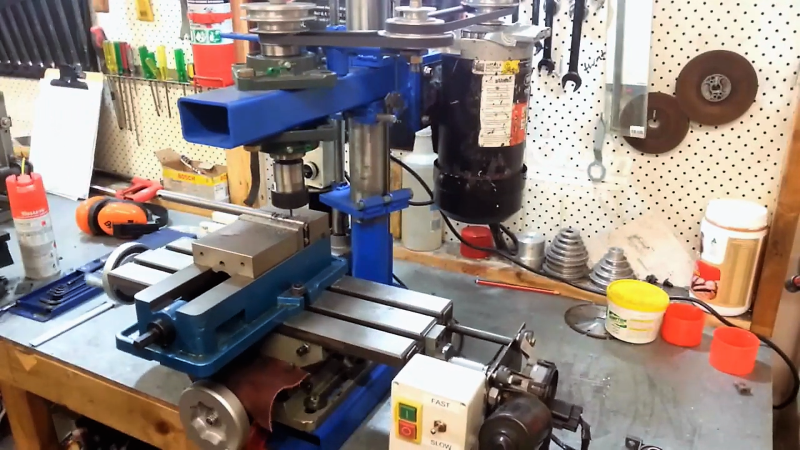
Details are a bit sparse in the forum post, but there’s enough there and in the video after the break to be mightily impressed with the build. Unlike many DIY mills that are basically modified drill presses, [Maximum DIY] started with things like a scrapped bench grinder pedestal and surplus steel tubing. The spindle motor is from a paint sprayer and the Z-axis power feed is a treadmill incline motor. The compound table was a little too hard to make, so the purchased table was fitted with windshield wiper motor power feeds.
Therein lies perhaps the most clever hack in this build: the use of a plain old deep 19mm socket as a clutch for the power feeds. The 12-point socket slides on the square shaft of the wiper motor to engage the drive screw for the compound table – simple and bulletproof.
To be sure, the finished mill is far from perfect. It looks like it needs more mass to quell vibration, and those open drive pulleys are a little nerve wracking. But it seems to work well, and really, any mill is better than no mill. Of course, if you’re flush with cash and want to buy a mill instead of making one, this buyer’s guide should help.


Strange use of time and money unless you only want to mill aluminum, brass, and similarly soft materials.
The metal removal rate for steel is going to be shit with that steel tubing construction for the Z axis, and the lack of a quill/Z-axis DRO is going to limit the ability to control depth with any accuracy. The spindle bearings + R8 taper look halfway cut out for the job, so that’s sort of interesting.
Probably a better use of time to buy an old used J-head Bridgeport with a trashed spindle and replace the head with a casting of epoxy granite with his spindle design inside it (assuming the spindle bearings could handle the increased loading of higher strength material removal.
I think I saw a bolted-on digital caliper on the Z in the last seconds of the video, not even close to a real DRO since it won’t have full-range but interesting nonetheless.
I think there’s a pretty good space for something like this. I don’t even think I could get the base casting of a J-head home, let alone all the way to my basement shop. That’s the kind of machine that needs to stay on the 1st floor on a solid concrete floor. Getting a few armloads of steel box section down there is easy though. I’d have probably filled the sections with something, whatever is the current material of choice. Concrete or fancy epoxy with fillers?
What makes you think you need a DRO for accuracy? I’m fine with a vernier scale, which would be fairly easy to make.
As to the steel tubing being too flexible, I won’t argue on that one.
Of course, it is perfectly reasonable to use a lathe for milling, especially if you only need to accurately position or move the workpiece in two dimensions. And I believe adding a Z axis to a lathe is not unheard of, which gives full milling capability. However, any such modification probably has fairly constrained movement compared to a proper mill, except in the dimension it isn’t normally needed!
At least he had a lathe to start with. There was an earlier post about a scratch-built lathe a few months back.
You can build everything in a machine shop with a lathe. It’s literally the most important piece of any machine shop. A high precision lathe and quality materials can provide you with everything you could ever need.
I would like to see one build a milli table with lathe. Unless you have a very large lathe, it wont be larger than a couple inches.
This somewhat leaves the boundaries of a normal lathe, but I needed a second spindle for my lathe so I could do things like drill evenly spaced holes in something I’d just turned, while it was still in the spindle and guaranteed concentric. Once I had a second spindle, I could bolt work to the ways, parallel to the lathe headstock/tailstock axis, and take light cuts along the entire length of the bed, using the carriage traverse as x and the cross-slide as z. It leaves a lot to be desired as a mill, but in my case my lathe is about 10x the mass of my tiny mill and has 4x the travel, so for some limited cases it’s a better option.
You buy a lathe first for people not trying to have sub standard equipment.
Making such a machine this way can of course be done for “fun” and I congratulate him for making a usefull mill but without being able to get most of the pars 2n-hand or cheap it is not really wort the effort (unfortunately).
A small (chinese) mill of this size costs around EUR1000, for example:
https://www.hbm-machines.com/producten/metaalbewerking/metaalfreesmachines/metaalfreesmachinesssub
(could also have posted a link to horrible freitht or whatever).
In this particular build I wonder how these parts were sourced (and their individual costs).
– Motor.
– XY- Table
– Pulley’s
– Morse Axle with bearings.
– ER collet holder
– Steel tubing parts.
Whats the price difference between those parts and a EUR1000 mill, and how much time do you need to spend to build it?
I’m not against building such a mill in itself, As a mater of fact I’ve done it myself.
I did realize though that building a “standard” machine such as this is not very time effective, so I built a machine configuration which can not be bougt of the shelf.
If you decide to build then I want to recommend to put more steel into your mill.
Rigidity is very important and you can never have enough, especially when using those big mills such as the mill with inserts at 5:00 in the video. Rigidity improves surface finish.
Also I find the idea of casting aluminimum in a round can, and then milling it flat again a bit … weird.
The “Lost PLA” way of aluminimum casting has been mentioned on hackaday multiple times and is much closer to the idea of casting “almost finished” parts.
Also, a tip for anyone considering a Lathe or mill:
Frequency inverters are pretty cheap nowadays.
If you want to buy a Mill / Lathe, then buy one with a 3-phase motor and add a frequency inverter.
Rotating a potentiometer is much easier then changing belts on pulleys, and it has another very big advantage.
You can use it for tapping with low RPM.
At low frequencies a 3-Phase motor does not have much torque (Adjustable with parameters in the freq. Inverter).
With my mill I can sucessfully tap blind M5 holes by putting a tap in the spindle and then slowly increasing the motor RPM untill the torque is just enough for tapping.
When the tap bottoms out, the motor stops because of the increased torque, which it can not deliver at those low RPM’s.
Also, Frequency Inverters upto about 1.5kW (mabe 3kW) can be bought with a single phase input, so you do not need 3-phases in your wall sockets to use such an inverter with a 3-phase motor.
It’s funny that here in the land of “Notahack”, the general consensus seems to be “He should have bought one instead”. Personally, I think that this is an awesome project. I’m not a professional machinist by any means, but I’ve spent enough time in front of a mill to know that for most simple hobby type jobs a mill like this will work quite well. Will it work at a professional level? Of course not. For that you need a proper professional mill. That being said, this thing is something that I would have appreciated in my own home shop, back when I had one.
I am a professional machinist, and I agree with you.
First- this is a hack, and I applaud his effort. Its awesome to see homebuilt equipment doing useful work. His ingenuity is wonderful.
I would say if you want to mill serious materials like steel, tool steels, titanium alloys, at any usable size and finish, know that you absolutely must have rigidity. There’s just no way around that.
The cutting geometry for those materials- you can cut them on even poor equipment with the right tool angles and materials, but you will never get anything even close to flat or cleanly cut in any usable way unless the stiffness and rigidity of your setup and machine are there.
As long as he accepts that fact, and never expects more of it, it’s still useful as a machine.
For the record- yes, you can mill on a lathe quite well, as well as use a mill as a vertical lathe.
I think it’s a whole different breed of maker that comments on DIY machine shop tools. No matter how heavy and rigid someone builds something, no matter what materials it’s made from, it’s never good enough for the machinists that come out of the woodwork to comment
The machinists tend to hate most of the professional hardware too.
It’s the voice of experience.
Do you have any idea how many hundreds of dollars in HSS and carbide endmills I’ve had to throw away because no amount of gib adjustment or tiny depth of cut will allow you to climb mill a reasonable finish pass on a <40 lbs X-Y table with the backlash of ACME thread lead-screws?
The chatter from attempting to machine mild steel will limit your depths of cuts and EM diameters so that you can only whittle away at material slower than an abrasive grinding wheel.
Machinists get paid to put metal on the floor. Your ability to make parts cost-effectively is determined by metal removal rate measured in cm^3 per minute. Your ability to machine even soft metals cost-effectively on a machine like this will have you upside-down economically in a matter of weeks if you value your time above minimum wage.
If you only need the tool for a couple cubic inches of removal of non-ferrous metals & plastic per year: by all means, cut corners and waste time accumulating tooling for a machine that will have you working at <10% efficiency.
If you don't enjoy scrapping parts, and want to work on parts larger than a model train: suck it up and put a used J-Head on the CC. The time-savings will pay the interest 10 fold.
Case in point.
Yeah, really. These people are talking about “cheap” mills that cost 1K+ USD, and complaining that this DIY one would be no good for heavy duty use.
Spoilers: I don’t have that kind of money to spend on a mill, and I’m not exactly going to be building rocket parts here. If I could build my own mill that was “limited” to just aluminum and brass, I’d be thrilled.
This is a great project, and honestly, it’s the kind of stuff this site is built on.
A bit of idea here. If you filled the voids of square tubing with epoxy granite or concrete, wouldn’t that made the machine a lot more rigid and overall stronger?
Yes, it certainly would. But then you’d have to read all the comments about how nothing but cast iron is good enough.
Filling it with cement or whatever will help with vibration. It does surprisingly little for rigidity. The stiffness of a cylinder (easiest to calculate but demonstrates the principle well) rises as the cube of its diameter. The stiffness of a tube is OD^3 – ID^3, so if your wall thickness is significant, you’re carrying all the strain on the surface and adding more material doesn’t add stiffness. Similarly, with the same wall thickness, you can make your whole machine of aluminum if the cross-section is increased by like 50% and have the same stiffness that steel would. It’s more expensive and much harder to fabricate than casting iron into a sand mold.
Note there are good reasons to build machine tools from cast iron, but cost is one of those reasons, while stiffness isn’t. Cast iron ways have very low friction and really great wear characteristics, and cast iron damps vibration pretty well.
There’s more information over at his post on Homemadetools.net. Has info about parts he made vs. parts he purchased. Also has this tidbit: