
No, you aren’t looking at a 30 year old Teac graphic equalizer that somebody modified. The MWA-002 Network Music Player created by [GuzziGuy] is built entirely from new components, and easily ranks up there with some of the most gorgeous pieces of homebrew audio gear we’ve ever seen. Combining modular hardware with modern manufacturing techniques, this 1980s inspired build is a testament to how far we’ve come in terms of what’s possible for the dedicated hacker and maker.
The enclosure, though it looks all the world like a repurposed piece of vintage hardware, was built with the help of a CNC router. It’s constructed from pieces of solid oak, plywood, and veneered MDF that have all been meticulously routed out and cut. Even the front panel text was engraved with the CNC and then filled in with black paint to make the letters pop.
Internally, the MWA-002 is powered by a Raspberry Pi 3 running Mopidy to play both local tracks and streaming audio. Not satisfied with the Pi’s built-in capabilities, [GuzziGuy] is using a Behringer UCA202 to produce CD-quality audio, which is then fed into a TPA3116 amplifier. In turn, the output from the amplifier is terminated in a set of female jacks on the player. Just like the stereo equipment of yore, this player is designed to be connected to a larger audio system and doesn’t have any internal speakers.
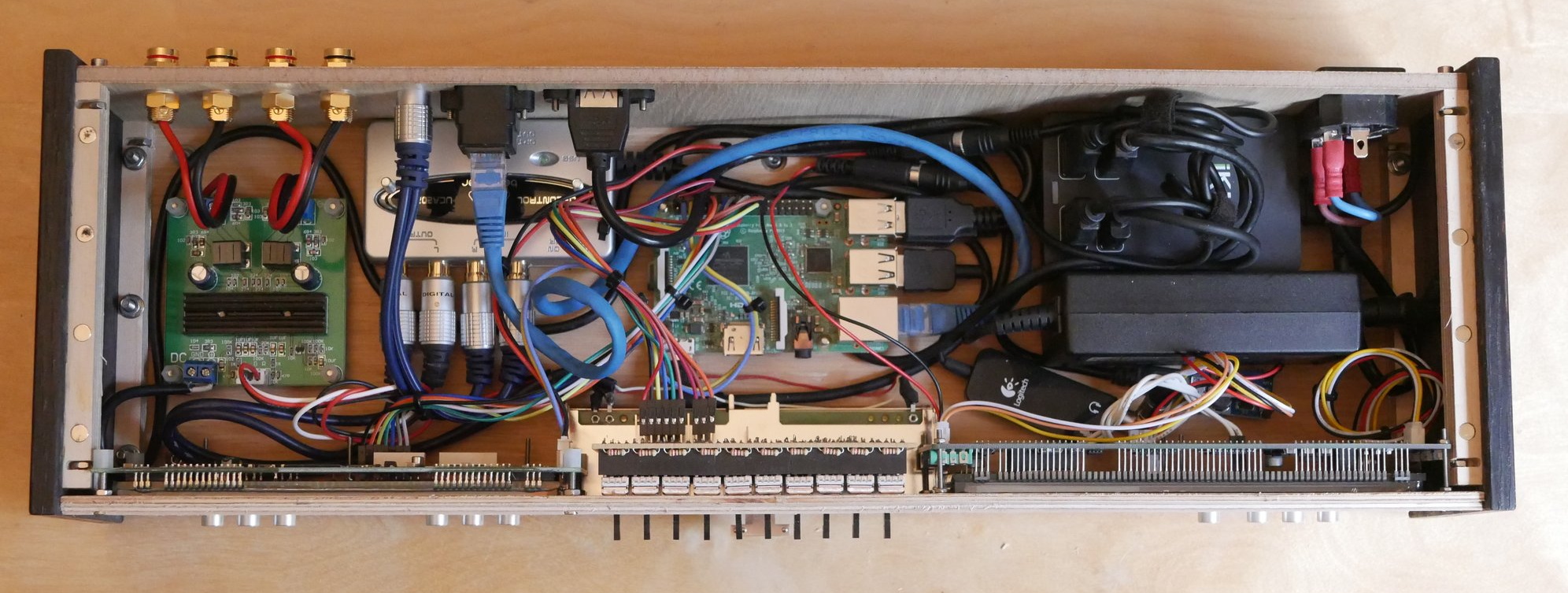
The primary display is a 256×64 Futaba GP1212A02A FVD which has that era-appropriate glow while still delivering modern features. [GuzziGuy] says it was more difficult to interface with this I2C display than the LCDs he used in the past due to the lack of available libraries, but we think the final product is proof it was worth the effort. He bought both the VFD spectrum analyzer and LED VU meter as turn-key modules, but the center equalizer controls are completely custom; with dual MCP3008 ADCs to read the state of the sliders and the Linux Audio Developer’s Simple Plugin API (LADSPA) to tweak the Pi’s audio output accordingly.
We’re no strangers to beautiful pieces of audio gear here at Hackaday, but generally speaking, most projects involve modernizing or augmenting an existing device. While those projects are to be admired, the engineering that goes into creating something of this caliber from modular components and raw building materials is really an accomplishment on a whole different level.


Wow yes, just yes.
Yep what he said ^^
Very fine eye for the 80’s electronics. The final element that proves it? The pushbutton that selects peak vs average on the VU display. Nicely done.
That front side looks gorgeous. I’d be proud to have made something that looks that good.
Darned shame the inside has to be that dog’s breakfast though.
It’s well organized enough for a one-off. I have been guilty of much, much worse.
My first thought was that they could’ve cleaned it up inside… but then, it all fits, appears to have left the components unmodified, and is much more tidy than if they weren’t contained in the beautiful case. Then I thought about watchmaking, and the intricate craftsmanship and decoration that only other watchmakers see… then I thought about how the most important part of the project is getting it done… further refinement of the interior would’ve taken more time, and might have even doomed the project. Maybe you should redesign the interior and build one to show off?
I’ll admit they could have used custom (I.E. shorter) cables rather than grabbing the first result on Amazon/eBay, but this is still a lot cleaner inside than MANY of the one-off projects we see around here. Plus plenty of room for air flow, though a fan would have been nice.
Just no.
Putting a fan inside a piece of audio gear is a kludge, wrong, and should *never* be done. Heatsinks, heatpipes and gap-pad – yes. Fans – no.
If you need a fan, you’ve done something wrong and need to rethink/redesign (unless you are talking hundreds or thousands of watts for a theater or rock concert)
Not dogs-breakfasty at all. The interior looks pretty clean and solid to me, and maintainable! which much custom hardware is not. My one small concern is the power supplies – do they leak any hash into the system? If not, then no problem.
The faceplate looks great. Well-done! It’s definitely more 1980’s Marantz than TEAC, btw.
I don’t know, I had a silver TEAC EQA-10 that looked a hell of a lot like this.
Well, doesn’t look like the dog’s breakfast to me. But I definitely would have removed the housing from the power supply and anything else that has it’s own housing. If only for the better management of the generated heat. But it also just looks a bit more professional too.
I thought so as first but this gives an extra layer of isolation of the mains which provides extra safety for a home brew project.
That is gorgeous.
No shielding between the bare audio wires/amp on the left and everything else. If there’s any EM noise bouncing around in there (from the raspi or the power stuff), it’ll get amped up by the amp board. It’s a beautiful-looking project that is sadly potentially flawed.
After reading your comment, I had to think about the WiFi onboard the raspberry pi…it almost always gets induced into speaker wires. I have to wonder if it was disabled? I believe Linux being different from windows, it must not be doing anything unless actively connected to an AP, where windows would be constantly pinging AP’s when not connected. I wonder if he hasn’t yet discovered that problem? Otherwise this build is amazing. I could have sworn the front panel was aluminum but it appears the *entire* thing is wood!
I’m more worried about the VFD on the left side (at least the link says it’s a VFD). Display modules like that generate a lot of EM noise because of the on-board power requirements.VFDs are gorgeous, I’m a huge fan of them, but the bare board that close to the bare amp board worries me.
Fortunately if the builders finds shielding-related noise issues, looks like there is more than enough space to add metal “walls” in places. Even if it’s just isolated and protected aluminium foil .
Want.
They don’t make’em like that anymore.
And in the 80’s-90’s you bought an amplifier chip, a VU-meter chip (or several) and used either a custom one-off display made in a Japanese factory or a ready made generic one. Perhaps one have to make each transistor by hand?
If you wish to make an apple pie from scratch, you must first invent the universe. : Carl Sagan
Wouldn’t “period correct” be one RCA jack per channel rather than the four female connectors seen here?
Shouldn’t something be done with the ground tab on the power jack or is that just my misconception?
“Shouldn’t something be done with the ground tab…”
Oh, heck no. In keeping with the general engineering quality and aesthetic of this build, the ground tab should definitely not be connected to anything, nor should a ground terminal be provided. It’s *meant* to permit the whole bundle of modules to float at half of line voltage, being capacitively-coupled via the power supply to both hot and neutral of the line.
The resulting 60 Vac on the chassis causes a pleasant tingling sensation when you touch the system, adding to the charm of using it. Or, if it’s actually connected to any other hardware, the ground current induced in those connections will lend it a beautiful vintage ground hum ambiance.
Now, you know that modern modular power supplies are very well isolated from the mains, right?
“isolated” in terms of withstanding voltage, yes, they are. However, modern supplies also must include capacitive filtering for EMCompliance. In the absence of a ground return path, the leakage current that filtering produces necessarily causes the output to float midway between live and neutral, and produces significant leakage current: tens of microamps in most cases. It’s easily detectable, and in almost all cases will fail the medical device leakage current limit of 10 uA.
It’s easy to check: take any two-wire mains-powered supply, and measure the AC voltage and/or the AC current between the power supply output and earth ground. From a 120Vac main, you’ll usually see more than 50Vac on the output, relative to earth, and at several tens of microamps current. It’s even worse on a 230Vac main.
It’s even easier than that to check:
1) Does it shock you?
2) Is there audible hum?
If the answer to both of these is “no”, then no, you really don’t need to ground it. Practice trumps theory, every time.
The hum stops when I touch it. Bad practice beats good theory every time.
The picture looks like it’s built to accept an extension cord. Can we talk about the RCA jack issue?
We could talk about the RCA jack issue, but there aren’t any RCA jacks. The jacks on the back are for banana plugs, for the speakers.
No RCA jacks on the outside, but there are the four on the inside, on the Behringer, *shudder*.
Then I noticed the TRS connectors for 5V power, which made me forget about the RCAs. Then I saw the USB headphone adapter flopping around at the bottom, right next to the barenaked power module rattling around there… Then I started looking for a dog without a breakfast.
No duct tape, baling wire or chewing gum though, so that’s good for a point or two.
I have an old magnavox amp / tuner unit that uses a 2 prong mains lead and a ground lug, and lol yes its case rides at ~45 or so volts if you do not ground it
back in high school (circa late 90’s) I left a key on it for shed door or something and I remember walking back to pick it up and that f*ker lit me up enough to hurt. It always would tingle you a little but picking up that key proved to be a repeatable whack … so I started keeping one on it all the time just to mess with buddies
Sooo, just how many times did you test this to make sure it was repeatable??? ;)
I never saw third wire ground on audio gear in the 80’s. They left the chassis to float or even worse with fender tube amps had a switch which would connect the chassis to one or the other sides of the AC line via a series capacitor and high value resistor.(yikes!) It was very common to have your hand on grounded guitar strings and grab a mic and get a small buzz.
Best practice is to ground tab the power supply to the third wire and let the chassis ground connect through a few ten K ohm to ground tab to prevent wall socket PPG differentials from inducing loop currents in the audio cables.
Best practice for low-noise power supplies was (and is) to use an electrostatically-screened transformer, with the (grounded) screen between the primary and secondary to prevent capacitive coupling from line to output. Then use a linear supply or regulator (no switcher) so line filtering is not required to meet EMC requirements, so there is less parasitic coupling from the line to the supply output.
A laptop power brick fails badly on both points. I’m looking squarely at Apple, whose power bricks have > 40 uA of leakage when ungrounded (e.g., using the “travel” cord or adapter). With the computer’s metal case, you get the tingles if you use it when not the computer is not grounded by something else plugged into it. Seriously annoying.
It *is* possible to build a modern switching supply with low (sub-uA) leakage current. It’s just bigger, more expensive and less efficient, none of which sell very well.
Yes.
Grounding a piece of audio gear via the mains connection is good for safety, not always good for audio – it can lead to ground loops, induced hum and other EMI. Grounding audio systems is a subject that volumes have been written on, and holy wars fought over.
Short answer is that
1 – you can’t earth a wood case ;-) and
2 – often the audio ground will be provided by other piece of gear in the system – eg audio sources, poweramp – which do have a connection to ground
The proof is in the pudding: if there’s no AC noise, hum, EMI in the sound, and you don’t get that tingle when you touch it….
Yes. Definitely don’t hard ground an audio chassis to a PPG unless you want a few amps of ground loop going through your audio shields when the upstream air conditioner kicks on. I watched an old analog video routing switch go up in flames when there was a power ground loop between commonly powered but physically separated buildings and the coaxes and BNCs were more than happy to try to equalize the voltages on the green wires. Current structured cabling spec avoid this but in a house it still is possible.
There’s more than enough original thinking in the overall concept and design, and the thought and effort put into the enclosure are far superior to most peoples’ efforts at “scratch-built”, which usually stop at spray-painted aluminum plates with panel-mounted components and maybe Letraset.
Again, my comment was not in any way about the project itself, which is a great job, and I would have to do at least a triple-take to even guess that it wasn’t packaged commercially. I also don’t even have any objection to using off-the-shelf modules. With most of these modules costing less than if I bought all of the components, they save both time and money, and in most cases perform as well as or better than if I designed them myself. My objection referred solely to [Tom Nardi]’s title.
What a ridiculous comment. There really is a hater for every project. Please explain what “mix” he used to create this? If it’s all paint by numbers, then show us another one just like it.
Meanwhile, a search of your name shows you’ve never created anything good enough to make it on this site where you belittle the creations of others. Shocker.
BigSadLoser: Did you not read my last comment? Of course, it’s hard to look up people who make up a new name for every comment. Dickhole.
Shiny!
Urg, using an outboard dac to drive a crappy class D amp chip.
For the curious newbie interested in audio, would you mind expanding a bit on what makes this amp chip crappy, and what decent alternatives could be chosen? It’d be fun to embark on a project like that but I’d have no idea how to pick an audio amp chip.
You could do worse than starting with a gainclone build. (Google it, plenty of ‘how to’s’ out there).
From a review site: “… the Texas Instruments TPA3116 Class D chipset which has quickly earned almost legendary reputation in audiophile circles.”
You mean THAT crappy Class-D amp chip?
Yup, that crappy class D amp. For real audiophiles class AB amps don’t really cut it. Class D amps excel at a few things. Power efficiency, and as an offshoots of that you can get a lot of power in a small light package. They have a lot of advantages in portable equipment. Things that run off of batteries for their power efficiency and sound reinforcement because you can get a lot of power out of a physically light package. However, the one thing they don’t excel at without qualifications (power efficiency, weight, size etc) is sound quality. I will grant you that they give you a lot of bang for your buck, but audiophiles tend to not worry so much about bucks and more about bang.
And you still did not suggested an alternative.
The so proclamed expertz/hackerz who only criticize without producing anything to the site are really shaming the community.
Being rude is not even an issue but not talking without backing up your words are more annoying.
Be still my beating heart…
@GuzziGuy, can you post your Futaba driver code?
you might have better luck if you wander over to his actual imgur post and ask there…
I wonder what a build like this would fetch on Etsy.