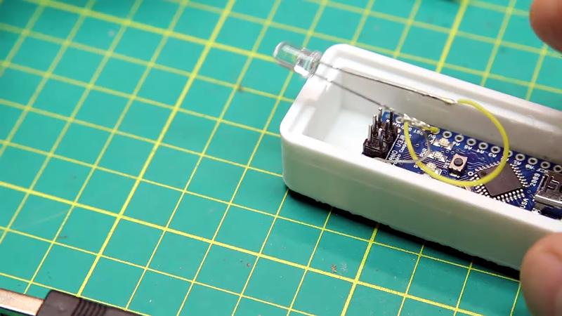
If you have a Roomba, you know they are handy. However, they do have a habit of getting into places you’d rather they avoid. You can get virtual walls which are just little IR beacons, but it is certainly possible to roll your own. That’s what [MKme] did and it was surprisingly simple, although it could be the springboard to something more complicated. You can see a video about the build below.
As Arduino projects go, this could hardly be more simple. An IR LED, a resistor and a handfull of code that calls into an IR remote library. If that’s all you wanted, the Arduino is a bit overkill, although it is certainly easy enough and cheap.
We know that’s not much, but we were impressed with some of the other information associated with the project for future directions. For example, there’s this project that adds an ultrasonic sensor to a Roomba using the serial port built under the handle. The interface and protocol for that port is even nicely documented.
That got us thinking. You could probably use some ultrasonic sensors for two-way communication to do custom walls. For example, you could use one to send a set number of pulses per second and have another device on the Roomba to receive them and count. You could program rules like a particular wall is only really a wall between 8 AM and 5 PM, for example.
We’ve seen some people use the Roomba as a general-purpose robot platform. We still wish we could find a sensor in the DigiKey catalog to help avoid this common problem.


Just when a project really can be done with a 555… :-D
555? A mirror or even a white item works fine.
My thought as well. If I’ve ever seen an example of under engineering (as AVE would put it, aka spending way to much to solve a problem) this would be it. So many super cheap super simple solutions instead it’s. Well if I get a Raspii and hook it up to a hadoop cluster I can start running machine learning on the images of the floor. Then when it sees the roomba I’ll turn a light on which I’ll train a cat to jump in front of the roomba when it sees the light on. Yep this is a reasonable solution for the problem.
will your 555 also blink an LED on the Arduino( ATTINY85 ) when the battery voltage starts getting low?
// from: http://forum.arduino.cc/index.php?topic=222358.0
// Attiny85 IR-test
// Attiny85 , running @ 8MHZ
// ATMEL ATTINY45 / ARDUINO
// Using DigiSpark instructions and AVR85 board
// Program using board type: Digispark 8MHz – no USB )
// R1=150 ohm(Br/Gr/Br) from GND with IR LED+(long) to P0
//
// +-\/-+
// Ain0 (D 5) PB5 1| |8 VCC
// Ain3 (D 3) PB3 2| |7 PB2 (D 2) INT0 Ain1
// Ain2 (D 4) PB4 3| |6 PB1 (D 1) pwm1
// GND 4| |5 PB0 (D 0) pwm0
// +—-+
// Vcc battery measurement: http://provideyourown.com/2012/secret-arduino-voltmeter-measure-battery-voltage/
// https://github.com/Yveaux/Arduino_Vcc
// https://github.com/pgollor/Arduino_Vcc mVolts and 1023 -> 1024 fix in Vcc.cpp
#include // for Vin voltage measuring used to determine Battery level
const float VccMin = 0.0; // Minimum expected Vcc level, in Volts.
const float VccMax = 5.0; // Maximum expected Vcc level, in Volts.
const float VccCorrection = 5.0/5.0; // Measured Vcc by multimeter divided by reported Vcc
void blinkLED(int pin=13, int blinkCt=1, int uSecDelay=200);
const int LEDpin = PB1;
Vcc vcc(VccCorrection);
void setup(){
pinMode(LEDpin,OUTPUT); //we’d want to blink the LED
DDRB |= (1<<PB0); //Set pin PB0 as output
TCNT0 = 0;
TCCR0A=0;
TCCR0B=0;
TCCR0A |=(1<<COM0A0); //Timer0 in toggle mode Table 11-2
TCCR0A |=(1<<WGM01); //Start timer 1 in CTC mode Table 11.5
TCCR0B |= (1 << CS00);// Prescaler table 11.6
OCR0A=104; //CTC Compare value
}
void loop(){
TCCR0A &= ~(1<<COM0A0); //off
delay(1);
TCCR0A |=(1<= fiveMinutes)
{
lastSampleTime += fiveMinutes;
// Do Voltage reading and Warning here
float v = vcc.Read_Volts();
int justV = v;
int justF = 10*(v-justV);
if( justV < 5 ) // less than 5.x Volts
{
if( justF <= 9 ) // Theshold value for low 9V source
{
// Warn of a low battery
blinkLED(LEDpin,justV,400);
blinkLED(LEDpin,justF,200);
}
// otherwise still in safe zone
}
// anything above 4.xV is considered safe zoon
}
}
// blinkLED
// default pin=13, blinkCt=1 and uSecDelay=200
void blinkLED(int pin, int blinkCt, int uSecDelay) {
for( int i=1; i1 || blinkCt==1 ) {
delay(uSecDelay); // +1 passes require delay of previous pass led LOW setting
}
digitalWrite(pin, HIGH);
delay(uSecDelay);
digitalWrite(pin, LOW);
}
delay(uSecDelay);
}
I guess you can have it blink a regular LED as well. If it gets dim, replace the batteries.
A simple voltage comparator can solve that problem without the need for an Arduino (or that long piece of code)
you’ll need a longer piece of wire and longer piece of solder too. But everyone knows what a comparator is, has one handy and knows how to setup the voltage divider needed. What was I thinking, Star Trek is real!
That’s what a power supply supervisor is for. :P
Just 3 pins – power, ground and active low output pin.
I have Arduinos and Raspberry Pis lying around my apartment. For any given project I can pick one up, write some code, and print an attractive case in less than a few hours.
Then maybe when I have time later I can build a custom circuit and order parts. But I rarely get to that point.
When I saw his article, I was initially thinking about a simple wooden plank. If it doesn’t stop the roomba via it’s sensors, it will certainly stop it from passing through. But considering that such a solution can be a hazard (tripping) this blinking LED solution is perhaps a bit better… It’s up for debate whether or not this arduino design can be simplified, but honestly, why bother, Arduino clones are dirt cheap, and a simple piece of heat shrink tubing will solve the need for a case.
I literally just tripped over hand weights we use to block off doorways, nearly broke my gd arm, my knee is swelling. Could definitely use some of these
Full arduino may be overkill, but I often use an AtTiny85 bare chip instead of 555 in small projects. It wins in requiring less external components, and is of course programmable as the project expands.
555 would work with a few other components besides the IR-LED but an ATTINY85 just needs a resistor(plus IR LED) and can be powered and mounted on top of a 9v battery. I use a straw to give direction to the signal.
Give 9V to an ATTINY85 and it loses its blue magic smoke.
I’ve got 6 Digispark ATTINY85 Arduino boards with 9V into Vin and no magic smoke… Maybe you thought I was talking about using an ATTINY85 chip.
“I’ve got 6 Digispark ATTINY85 Arduino boards”
So you got an ATTINY85 plus a few other components besides the IR-LED.
“555 would work with a few other components besides the IR-LED”
It’s an Arduino compatible board and can be purchased for $2. I would expect people to understand a few lines of code before expecting them to know how to read the spec sheet on a 555 and purchase the correct resistors and capacitors to make the circuit work. And then there’s the soldering skills… Why aren’t you guys crying about this not being down with discrete transistors? gawd
“an ATTINY85 just needs a resistor(plus IR LED) and can be powered and mounted on top of a 9v battery”
[sarcasm] Yup…..that sounds nothing like a 9v battery powering an ATTINY85 [/sarcasm]
And you people can’t figure out that it was an Arduino compatible attiny85 board? Jumped to the conclusion it can’t be true because an AVR ATtiny85 chip only works 5VDC or less? clowns… https://www.aliexpress.com/item/32236289635.html