Mechanical keyboards are all the rage right now, but the vast majority of them are purchased commercially. Only the most dedicated people are willing to put in the time and effort required to design and assemble their own custom board, and as you might imagine, we’ve featured a number of such projects here on Hackaday in the past.
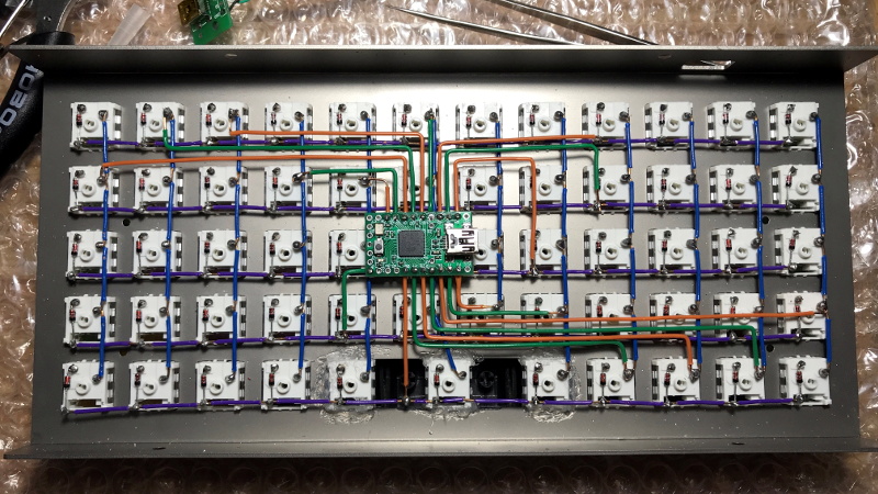
 But what makes this particular mechanical keyboard build from [kentlamh] so special isn’t the final product (though it’s certainly quite nice), but the care he took when hand-wiring all of the switches to the Teensy 2.0 microcontroller that serves as its controller. There’s no PCB inside this custom board, it’s all rainbow colored wires, individual diodes, and the patience to put it all together with tweezers.
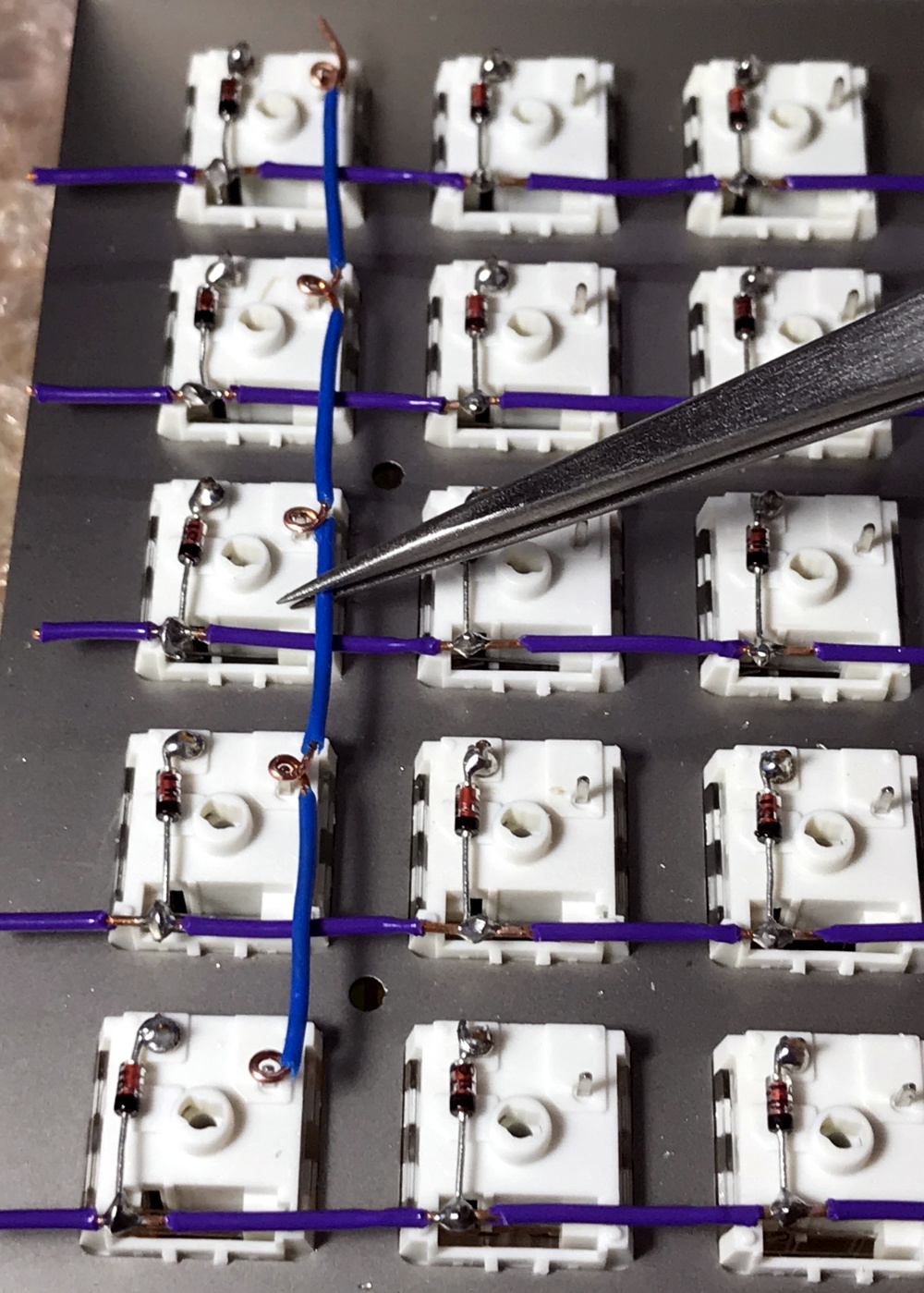
[kentlamh] takes the reader through every step of the wiring process, and drops a number of very helpful hints which are sure to be of interest to anyone who might be looking to embark on a similar journey. Such as bending the diode legs en masse on the edge of a table, or twisting them around a toothpick to create a neat loop that will fit over the pin on the back of the switch.
He also uses a soldering iron to melt away the insulation in the middle of the wires instead of suffering through hundreds of individual jumpers. We’ve seen this trick before with custom keyboards, and it’s one of those things we just can’t get enough of.
Some will no doubt argue that the correct way to do this would be to use an automatic wire stripper, and we don’t necessarily disagree. But there’s something undeniably appealing about the speed and convenience of just tapping the wire with the iron at each junction to give yourself a bit of bare copper to work with.
Even if you aren’t enough of a mechanical keyboard aficionado to travel all the way to Japan to attend the official meetup or discuss the finer points of their design at the Hackaday Superconference, there’s an undeniable beauty to this custom board. With a little guidance from [kentlamh], perhaps it will be your own handwired masterpiece that’s next to grace these pages.
[Thanks to Psybird for the tip.]


I wonder if extremly low current TIG welding could be used instead of soldering. That would make for a much better connection.
Resistance spot welding is common for e.g. battery terminals but has also seen use for other smaller components.
Can’t really see TIG welding being applied for assembling electronic parts though.
free hardware!!!
A good application for Verowire I would have thought?
I used magnet wire for mine, no stripping necessary. I’m astonished people are willing to put so much tedious work into perfectly stripping ordinary wire.
Doesn’t magnet wire have enamel coating, which is like hard insulation? Removing it is even more diffucult than normal insulation. Unless you remove it during soldering itself, in which case you make a very dirty and possibly unreliable joint.
the burnt enamal coating can easily be removed with a cloth and some rubbing alcohol also the joint is pretty reliable when soldering the thought the enamel coating.
It would be cool if someone did a microcontroller less keyboard, using TTL chips to bitbang ps/2. I don’t think any hobbiest has done that before.
This is the hobbiest idea I ever heard.
TTL bitbang USB.
I don’t think that’s possible. usb frequency is around 24mhz.
I really want to make my own keyboard with cherry keys, custom shape and design. But I am concerned I will botch something beyond repair and just waste money.
Is this kind of project something a complete noob can accomplish?
Heck ya man! It’ll take a little practice getting the timing right on soldering, but switches are ~$1 these days, so it’s totally worth going through a few to get the hang of it.
Getting started with wiring up one of those 9 button ‘cherry mx switch test’ board might be a good place to start. That plus a $20 teensy and some diodes could turn into a cool mini stream deck, yamean?
If you’re the kind of person who can’t find his arsehole with both hands i’d say it’s not for you, but imo there are so many different approaches to builds that anyone can bang something out. For instance not everyone can grasp 3d modelling to generate files for cnc machining, but I’ve seen a guy who made a case with nothing more than a welder and grinder. If carpentry is your thing many builds are carved out from a block of wood.
There’s automatic software for switch plate generation and companies which will gladly make those plates and post them to your door. Then there’s a guy who was featured here before who drilled and filed out a plate by hand. that’s not high tech or expensive.
I’ve been thinking of doing my own custom board for a project, probably 3D printing the plate for the switches and just wiring it up by hand like this. It definitely takes quite a bit of time, but there’s very little that could go “wrong”. In the absolute worst case you blow up the MCU, but they are cheap as dirt anymore.
There are PCBs out there that already have controllers on them and will save you A LOT of manual work, but of course they are all of a standard rectangular design. If you’re looking to do something outside of the normal, hand wiring probably will be your best bet.
One of my first projects was building a mechanical key switch keyboard:
http://hoalabs.com/mods/chairkey/
This started with a real keyboard that I had to pry the keys out due to being long enough ago that just ordering a bag of cherry MX wasn’t a practical thing and reverse engineering an off the shelf keyboard wiring instead of using a microcontroller. You’ll probably pull a few of the leads out by overheating, but as long as you buy a few extra you should be good.
He says in his caption that he marks the spot with his iron and removes the insulation with a knife.
I would have used at least the across buses to be bare wire. Double insulation here is an overkill, but even easier use all bare stiff enough wire on all the short jumps. Nothing will move the short stiff wires inside here if enclosed. CAT3 phone wiring makes great jumper wires in breadboards and point to point. There is some almost anywhere telephones used to be hooked up. The stuff used in wire wrap and board repair is too fine to use here this way.
I have three keyboards of switches like Cherries and want to make an Axis 6X6 style music keyboard, so that’s the way I figured I would do it. Also use two headless pins stuck in a piece of soft wood to make a jig for any small repetitive wire bending job.
Melting the insulation is a good trick, but a little messy for my taste.
When I need multiple contacts along a wire, I strip a couple inches of insulation off the end, decide how much insulation I want for the first segment, and cut that much from what still remains on the wire. Then I solder the first joint, slide the cut insulation along the wire to meet it, and solder the second joint. Then I cut another chunk of insulation, slide it along the wire until it hits the second joint, solder the third joint, and so on.
It isn’t too bad once you get used to it.
Yep, elongating the metal core just to unstick the isolation and then cut at correct length the section is much cleaner than melting it, for simpler wire jumper it’s also nicer to slide the isolation a bit, cut both the insulator and the wire at the correct jumper length, then pull back the insulation on the middle. no mechanical mark at all on the metal core like that.
This make video shows a bit the concept but it lack some tip to make it better…
https://www.youtube.com/watch?v=ver-Av8vr1Q
I take 1-1.5m sections of wire, strip both end. stick one end into a vice, I pull on the other with a pliers, just 1-2cm is enough, this unstick the insulation and you can easily move it after. I pull back a bit the insulation to expose twice the length of the copper end I want, then cut both the core and insulation at the expected insulation length, then I only have to move the insulation in the middle of the new jumper. If you take care to trim the first parts you stripped, all the rest of the core is pristine, without any stripping mark at all, and it’s easy to do some perfect sized wires like that, it’s quick too once you prepared your 1m section, just slide the insulator a bit, cut the whole at length, slide back the insulator and done, just one cut, no other tools involved…
You technically don’t need insulated wire if you want to save yourself even more time in the assembly. ;-)
Those who want to learn more about custom boards, should check out deskthority or geekhack forums.
FWIW, with many projects like this one, you can just use completely bare wire, then insulate it after you solder it. In this case, you’d first lay down one direction then coat it with varnish/liquid electrical tape/etc., followed by the second direction. (You can also solder one point, slide on some heatshrink tubing, then solder the next point.) Solid CAT5 wire (0.5mm) is nice for this, and RG-59 (0.75mm) or RG-6 (1.00mm) cores are great if you want something partially structural, especially if they are copper-coated steel.