We’ve seen a lot of motor driver boards for robots and the odd electric skateboard. What we haven’t see a lot of is one big enough to drop into an electric vehicle.
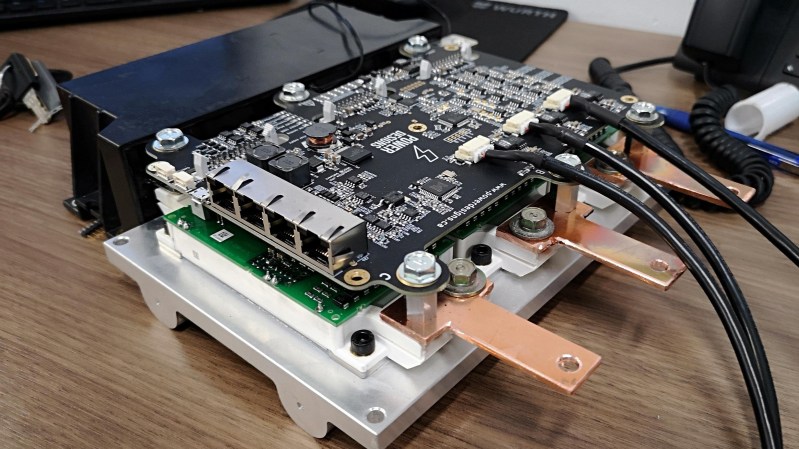
The Axiom motor controller was a winner of the bootstrap contest and is a Finalist in the 2019 Hackaday Prize. The driver aims to deliver 300A continuous at 400V all day long. Which is a very impressive amount of power from a board that appears to be quite compact.
The brains of the device is an ice40 FPGA from Lattice running software based on the VESC Project. Its open source roots will certainly allow for some interesting hacks and an increasingly stable platform over time. Not to mention the existing software tools will aid in the sometimes cumbersome motor-driver tuning process.
The board designs are available, but we agree with the team that the complexity of assembly is likely going to be high (along with the price). The amount of research and skill going into this complicated kit is a bit mind-boggling, but we hope it will really enable some cool hacks, from cars, to ATVs, and maybe even an electric flyer.


Getting closer and closer to an Open Source EV toolkit… and maybe even something like an Open Source EV “Crate motor”
I’ve got a ’78 International Scout that I would *LOVE* to run electric…
You may want to start shopping for leaf drive units, you get good deals if you can wait. Arlin’s drive units were like $500 including gearing and diff IIRC. A large induction motor is cheaper but there isn’t FOC support yet.
I wonder if anyone has come up with a limited slip differential or locking differential for the Leaf yet.
The obvious question is, why? When would you need it?
One case would be snow and ice, but the Leaf doesn’t have active thermal management for the battery, so it’s pretty sketchy to use anywhere it really gets snowy.
To launch faster. Racing, and specially dragstrip applications have very limited slip diffs, I’ve seen dudes that just weld the internal diff gears for quicker launches. Can’t afford to have one wheel spinning like crazy. Its also why several folks are interested in controlling each wheel with its own motor.
I texted arlin yesterday about this to reply Joel, as he mentioned something about the diff he is going to install. IIRC these nissan parts mate well with each other, for example the CRX has a big brake kit coming from a nissan 240sx (or something like that) that mates with the leaf drivetrain. I’m pretty sure there was an LSD that can work with the leaf.
Wrong. Leaf had thermal management for cold weather.
I’m unfamiliar with Arlin, and pretty new to this kind of wrenching. My Googling skills seem to be failing me here but I haven’t had time to really dig in. Where should I be looking for these magical cheap Leaf drivetrains?
Generally on ebay, a quick search right now returns this item: “Nissan Leaf Engine Electric Traction Motor Assembly OEM 39K Miles Yr 2012” for $849.98 USD.
But if you keep searching over time you will find better deals, which don’t last for long.
Still, $850 is not too bad for a motor capable of 300hp that includes reduction gear and diff.
Nice! Thanks so much for the reply
Not to beat a dead horse, here, but you’re a knowledgeable sort whoseems inteested in sharing knowledge on the matter: Where’s a good forum or wiki or community whatever where an internal-combustion car guy might be able to bone up on the EV workings, if I am to start to take this project seriously?
I would say general and down to earth information about EV conversions is in diyelectriccarforum. Endless-sphere forums is a bit more involved in deeper techincal aspects, and is focused on smaller e-bike class vehicles.
Thanks much!
Actually, the assembly dead simple. Literally a bolt-on the powerstage transistors and DC Link.
And the brains is still the common STM32F4 we all know and love, the fpga is there for safety functions and maybe some advanced features in the future, but for now all the fun happens in the microcontroller.
Don’t miss taking a look at the schematic!
I get the impression that they mean “assembly of the controller board itself” rather than “assembly of the controller within an EV application.”
Some projects just make you chuckle about pushing the boundaries.. 300A continuous at 400V !
Do we have any idea what the price will be like? $100? $1000? $10,000?
Based on discussion I have seen in the past, I think it’s going to be in the $3-5k range, which is similar to the cheapest off-the-shelf controllers with similar specifications. Of course it depends a lot on volume and the level of technical support. The selling point is that it runs open source software with great tools, compared to the rigid interface and lackluster tools from the commercial competition. FWIW I would gladly pay $5k for this, given that a team I worked with in college paid more for less just a couple years ago.
I think that would be right. In order to sell many, first the installation and setup needs to be straightforward as we can’t deal with too many customers asking for step by step support. Support is probably the reason why the big controllers out there are mostly sold to companies and not so much to end users. If Axiom has an extensive public documentation and valuable build logs it may have the chance to reach a much wider audience, not for the sake of selling more boxes, but to make an actual technological impact.
Some projects just make you want to vomit blood from the amount of self promotion yet non delivery of product. I am really what makes something that is mostly built out of (and I quote) EconoDual IGBT modules because its a popular package, they come in many voltage and current levels (from 600V to 1700V, and from 100A to 1000A), from many brands, in both IGBT and SiC technology and with available off the shelf gate drivers matched for them, so rare, that they are selling only a ” tiny % of them” that have requested them. “Picking the most equipped engineering teams capable of providing us with valuable feedback to make sure we deliver a solid product” This sounds like a quarter baked project that they can not afford to manufacture or test. After reading their blurb they make Elon seem like a straight up kind of guy.
I invite you to come up with something better!
I think what the op is trying to point out: your entire build log sounds pretty pretentious. Maybe it is a cultural thing. I don’t know. But also for my (European) ears, your writeup is too pretentious whilst having delivered not really more than some prototypes. An example is the quote the op was mentioning: “only the most equipped engineering teams capable… bla”; Phew – gimme a break. Who do you think you are? You are bragging about what? About the fact that you just were not able to deliver more prototypes?
It’s not about your project which I personally find very interesting and cool. It’s about your style of writing and your attitude. Don’t shameless self promote you of your work before it is really done (hence the reference to Mr. Musk). This can be (and obviuosly is) perceived as bad style.
I appreciate the feedback, if I’ve had it earlier in the game I’m pretty sure we would have dialed it down. What we are after is testing with as much different motors as we can, and we don’t have the budget to order 10 different $5k motors so for now we pick the users, ship boards and help them as much as we can, and believe me that I can’t support more than 10 people at the same time with different setups.
Main issue when this started was sending boards and never see them landing in a bench, thats a big loss for the product development
Shop around for hybrid Toyota/Lexus transmissions. If you can find one close enough to pick up, it’ll get you two high-power BLDC motors for under 1K.
2 guys are using a toyota transmission. One didn’t go too far, the other had a spinning motor but ran out time for a race event I think.
There aren’t many EV’s in my country so hopefully my mates will have a better chance at getting one of those. Right now I’m importing a customer’s 100kw motor into argentina and the paperwork is ridiculous.
What nonsense BeatJunkie. The guy has an interesting project. If you don’t like his promotion, then stop reading and go elsewhere – or try to replicate it. This kind of intolerant social puritanism and holier-than-thou attitude must be quite European and socialist. Here in N.A., we don’t chastise people for their style. We look at the substance.
FWIW, we are involved in something different, but a lot of the key parts are the same. As you said the parts to deal with the high power are off the shelf, and hopefully are over rated enough that they can take some abuse. Dealing with high power as Mr. Crey put it, is as much of a cooling problem as anything else. At some voltage level you need to deal with large amounts of airspace and insulation, but you are not there with this. I would assume you monitor the current through and the voltage across your output devices and the temperature of your cooling system. We don’t deal with motors, but I would assume a 3 phase motor drive the differences between the phases are consistent. It does not seem hard to generate them. I would assume you are using some type of PWM to drive the motor phases, again, nothing hard there. Does your product allow for regenerative breaking? That might make it more interesting. As I said, we have a totally different product but your product does not sound like it has a lot of challenges we have not faced. You perhaps face the nasty environment of being in a car as far as vibrations and temperature extremes go. We face the issues of never knowing what the exact load is going to be, and the possibility of the load changing or even being removed while in use. We have done a pretty good job of making it bulletproof. If your product is bulletproof, why does it need so much hands on support?
Yes, desat (aka short circuit) and undervoltage protection are in place on each IGBT, we measure the temperature of each IGBT module and the DC Link. Plus each phase has overcurrent trips implemented in both software and hardware, same for phase and DC Link overvoltages.
To avoid ridiculous (40+%) custom taxes most of the teams got only the control board so they assembled the controller themselves. It took us a while to have our own dc link design, so most controllers had DC Links sort of hand made by the users, that was a #1 fail as they had poor ESL and high EMI. This is not a problem anymore but it took time to sort out.
Another challenge is to obtain the rotor position. You want 3° of accuracy and resolver analog frontend takes some effort to calibrate, but even then the interface can be too slow and require to rely on a sensorless observer at high rpm (60kerpm for example), which based on motor parameters and analog feedback estimates the angle.
There are tons of algorithms out there, but VESC observer is based on ideal motor models with parameters like phase resistance, inductance and flux linkage, which we want the controller to be capable of measuring on its own. Now measuring 20mOhm with a +-600A range sensor and +-650V range voltage sensor is challenging. Get it wrong and motor won’t even spin. Most of the times it works right away for low loads, but when pushing to the power limits the observer can trip and that requires some manual tuning. Why is that? Well, resistance changes with temperature, and inductance drops when the high current starts saturating the motor confusing the angle observer. We have correction factors to compensate those effects, but you can imagine how a nice perfect model starts to show its quirks and every motor topology is different. Axials are low L (require high sw freq), IPM needs MTPA and FW, high pole counts come with poor position feedback.
End goal is online parameter measurements, so you are continuously refreshing R, L and lambda, but we are not there yet. TI I think implemented it, but their code and algorithms are hidden in their silicon.
And yes, vesc does regenerative breaking but its an overrated feature, once you get field oriented control, positive or negative (regen) torque is just a matter of changing the sign of the torque command.
If it were as easy as you make it sound, somebody would have done it before. The devil is in the details, and he is a nasty one at that. This project is great news for people who want a powerful motor controller that doesn’t suck to integrate into a system (or cost multiple arms and legs). The tone of their writing reflects the fact that they know how people feel about it.
Maybe you are a genius who turns out robust 50kw+ motor controllers in his sleep, but for the rest of us mere mortals it is exciting to watch the progress. And progress it is. There are plenty of technical details for anybody who cares enough to look.
I’m glad they have put effort into promoting the project for multiple reasons. First, projects like these need publicity to succeed, and I really want it to succeed. Second, the effort they put into promoting the project means lots of well-written information about the project.
You really need to get used to how marketing works. Everything they have written is spectacularly down-to-earth and informative compared to any commercial product.
Marketing was clearly out of my comfort zone, but it was a main premise in this year had prize so its an opportunity to push our own boundaries. We wouldn’t have made a video or a mailing list without the contest for example.
Thanks for your support!
-10
300A at 400V? No thanks. Maybe it’s the applications I’m used to dealing with (few hundred amps, , 270VDC & 3-Phase 115VAC, a 20kft or higher) but I don’t trust that thing to not arc-over from the line to neutral OR to not melt & smolder from the current. It just doesn’t look like it’s sized right to not kill someone, not without more insulation and thicker copper. I’ll pass.
In what particular part would you say it will melt at 300A?
Is 8mm cleareance/creepage between power and logic not enough? There is a second isolation barrier if you control it over the isolated CANbus. Is 5kv rated isolators and transformers not enough isolation?
8mm clearance for 400v? Oh heck no that’s not enough. 400v has this habit of jumping air gaps wider than that. Electricity acts in interesting (deadly) ways at high voltage where insulation breaks down. When dealing with HV, you can’t just look at the circuit diagram but how the whole thing is physically constructed. A little dust it dirt on top and you wind up with an arc and a really bad day.
As for”what might melt”, start with that thin busbar. I use thicker for 200A.
Please take a look at: “Isolation in AC Motor Drives: Understanding the IEC 61800-5-1 Safety Standard”
http://www.ti.com/lit/wp/slyy080a/slyy080a.pdf
In particular, Table 1. Summary of requirements per IEC 61800-5-1 for a few example systems (Category III, pollution degree 2, altitude <2000 m)
8mm is enough to comply as reinforced isolation with 400Vrms working voltage. 8.3mm gets you to 830Vrms with basic isolation, and that's without using conformal coating.
billyg, i hear what you’re saying and i know the issues you speak of. i’ve designed a lot high power applications in a fully military qualified lab where things such as what you speak of are known. they are also mitigated in ways by designing to relevant standards for creapage/clearance at the altitude or environment intended, careful component selection. methods such as, but not limited to, conformally coating, assembling in a clean room, hi-potted and/or dielectrically tested, water tight enclosure. we don’t really talk about the 20 years of work relevant work experience we have designing for real applications and real specs where one has to prove by analysis and test a tonne of stuff like, but not limited to, shake & bake, EMI scan, accelerated life test, and all the tests you do for automotive qualified or its equivalent testing for product durability against voltage transients and whatnot. it’s intense what is happening behind the scenes that are not really discussed in the forums or web blogs. but as you can imaging, there is a hole product evolution that has to happen to ensure fitness of purpose.. in the end, to make it reliably safe so that interested members of the public can have confidence in a product.
Actually on second thought @billyg may very well have a good point. Think inductive load under heavy load that for some reason has a dodgy joint go intermittent. The back emf could very well hike that voltage much much higher. It is the unusual ie fault conditions that usually bring us unstuck…. maybe there needs to be some sort of calculated 5mm spark gap to take the energy out of such an event? Just saying but great project!
What I overlooked in billyg comment is that he said 20kft, my brain never realized he meant 20,000 feet, which after looking up is >3,000 meters.
Above 3000m the clearance/creepage requirements go wild and you need lots of extra measures to comply with regulations. Axiom isolation was calculated for lower altitude applications, I think we can workaround the issue with potting but may very well require a redesign.
@dingodreams the overvoltage you mention happens on every switch due to parasitic ESL, take a look at the powerstage validation log to see in detail that event. You must ensure the overshoot stays below the IGBT voltage ratings.
In the event of an abnormal or intermittent joint that could produce a spark, or excessive regen, some gate drivers have a crowbar circuit that turns ON the igbt when the voltage is too high. In that case the IGBT avoids an instant death by voltage, and goes for a slower death produced by the heat from a short circuit. Hopefully the IGBT will survive the thermal surge and live another day.
The gate drivers we design have this crowbar, but Axiom off the shelf gate drivers don’t. Thats something we may improve in the future.
I honestly cant tell if you have actually ever built anything related to power electronics or are just looking to shit on random projects. 8mm creepage is more than enough for these voltages, not to mention 8mm clearance. And that’s before you add any sort of conformal coating. The bus bars look on the order of magnitude of what you want, nothing you could judge by a photo, either way.
400V is almost the peak on a 240V AC line, its barely high voltage.
The signal cables should not be draped over the bus bars but thats beside the point and probably just for testing.
Cool work Marcos! Its nice to see more people doing power electronics work, its an underappreciated field.
Good timing, I’ve been idly looking at my dead scooter and thinking maybe it’s time for an electric conversion :-)
That will make one heck of a fast scooter!
I bought 4 large heavy duty brushless motors with resolver feedback at an auction a few years ago and have been on the lookout for controllers for them ever since. Very glad to see this supports resolvers!
I can’t wait until these are more available. Looking forward to finally building an all wheel drive electric buggy!
Does this take care of everything?
It’s turn key, just add batteries a motor and a pedal ?
Or are more brain boxes required to say add to a leaf motor ?
What about twin motor, two boxes, and use the CAN bus to link them but share the same battery pack (built for max draw of two motors) ?
We plan to provide a fully enclosed unit next year. It would require external wiring, contactors, fuses and ~12v supply. And you should want some BMS integration.
2 controllers can talk to each other over canbus and apply some simple traction control. Someone asked a week ago if the code can support 4 controllers (one per wheel) and after looking at the code I think it can, but didn’t test it yet.
Sonny is an author of a honeywell patent for improving the system loading when multiple motors share the same DC bus, so there are some ideas that we would love to implement on this platform.
If you’ve got people involved in the project on the pay roll of companys like honeywell I trust that you are distancing from their rules on ownership of the ideas their employees come up with in their spare time.
I’d hate to see your hard work part owned by some large corproation due to a vague contract and you not having enough money to fight large legal counsel.
I know how difficult is to get something like this done in Argentina and all the hoops you must jump through to purchase equipment or parts. Well done.
Yeah we carried the IGBTs and heatsink of the first build throughout our whole honeymoon to avoid the corrupt Ezeiza. Got quite a neck injury right there.
And yesterday I lost 6 hours doing paperwork to import an aircraft motor for a client that needs double pulse testing and high power tuning. Paperwork continues today, still without a clear solution. I’m hoping to win HaD prize to slap some politicians and maybe who knows, change this utter BS.
Hii Guys!
I was thinking to use this motor controller for my 110KW 400A 300V BLDC motor…
can i use this VESC in my project?
Please let me know anyone.
Regards
Arun