It’s taken longer than some might have thought, but we’re finally at the point where you can pick up an SLA 3D printer for a few hundred bucks. These machines, which use light to cure a resin, are capable of far higher resolution than their more common FDM counterparts, though they do bring along their own unique issues and annoyances. Especially on the lower end of the price spectrum.
[FlorianH] recently picked up the $380 SparkMaker FHD, and while he’s happy with the printer overall, he’s identified a rather annoying design flaw. It seems that the upgraded UV backlight in the FHD version of the SparkMaker produces somewhat irregular light, which in turn manifests itself as artifacts on the final print. Due to hot spots on the panel, large objects printed on the SparkMaker show fairly obvious scarring.
Now you might expect the fix for this problem to be in the hardware, but he’s taken it in a different direction. These printers use an LCD panel to block off areas of the UV backlight, thereby controlling how much of the resin is exposed. This is technique is officially known as “masked SLA”, and is the technology used in most of these new entry level resin printers.
 As luck would have it, the SparkMaker FHD allows showing various levels of grayscale on the LCD rather than a simple binary value for each pixel. At least in theory, this allows [FlorianH] to compensate for the irregular backlight by adjusting how much the UV is attenuated by the LCD panel. He’s focusing on the printer he personally owns, but the idea should work on any masked SLA printer that accepts grayscale values.
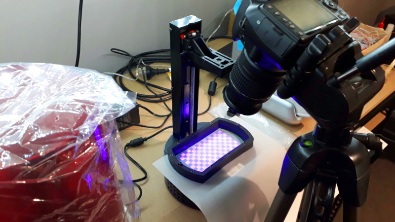
The first step was to map the backlight, which [FlorianH] did by soaking thin pieces of paper in a UV reactant chemical, and draping them over the backlight. He then photographed the illumination pattern, and came up with some OpenCV code that takes this images and uses the light intensity data to compensate for the local UV brightness underneath the sliced model.
So far, this method has allowed [FlorianH] to noticeably reduce the scarring, but he thinks it’s still possible to do better. He’s released the code for this backlight compensation script, and welcomes anyone who might wish to take a look at see how it could be improved.
An uneven backlight is just one of the potential new headaches these low-cost “masked” SLA printers give you. While they’re certainly very compelling, you should understand what you’re getting into before you pull the trigger on one.


I wonder if it would be possible to use a similar process to print a grayscale shadowmask on a transparency sheet with a regular inkjet printer to do a similar job?
Maybe use the same UV reactive stuff as above and then with a scanner and a little image manipulation, a mask could be printed out and laid down between the printer and resin tub.
Incidentally this process is used in the manufacture of OLED panels. A ‘raw’ OLED panel will have an uneven light output (known as ‘Mura’) due to minor unevenness in the organic film deposition process having a large effect on individual subpixel response. Every panel thus goes through a calibration stage where a series of test patterns is displayed on the panel and captured by a high resolution MV camera, and this sued to create a per-pixel inverse transfer function of the panel that is store in that panel’s controller and used to modify the values sent to the panel at display energisation time.
This is also why the Vive Pre had infamously atrocious Mura: to speed production of the initial batch only the most cursory calibration was performed (normally the panel would do through environmental cycling first to ensure the organic layer had fully cured and bonded and was not going to physically change any further) in order to get the first panels off the line as quickly as possible, and this bit them as by the time those panels were shipped and integrated within the HMDs the OLED panels had stabilised out-of-calibration and the Mura had returned. This also had the most irritating effect on the VR community where laymen refer to any sort of panel issue as ‘Mura’ (I’ve seen people referring to fill-factor – and even contrast ratio! – as ‘Mura’, which makes no sense whatsoever!) making it almost impossible to discuss specific artefacts with the proper terminology.
Hmm.. neat. So these are just panels that haven’t been dialed in? Or are these panels not OLED and that’s specific to OLED?
It’s the same process (photograph the finished stack, compensate for nonuniformity in software) but for different reasons. For OLEDs it’s due to the manufacturing process, here is due to the backlight not having the proper diffuser.
I have this exact model printer (from the kickstarter) and an Elegoo Mars. I had a very early LCD failure, like less than 30 hours of operation. Replaced the LCD and cooling fans and its working better. I was getting weird patterns on prints that were flat to the plate and LED array, but have not seen them since replacing the LCD mask, surprisingly. But quality control is kind of hit and miss, the FHD has some that will manifest different lighting flaws. Yet even at the worst they were only visible on flat parts, and for printing gaming minis or models with detailed surfaces, the sorta blurred hex patter thing isnt visible.
I wonder what effect, if any, of more greyscale use will have on the lcd’s longevity. they already dont like the exposure to the LEDs and heat they experience.
The grey scale shouldn’t affect the longevity too much. Most of the pixels are black most of the time anyway during print. The effect is most prominent on gently sloping, smoth surfaces. High detail minis aren’t affected very much. It’s a little tricky to get a good reading of the backlight intensity since it is highly dependent on the angle you are capturing it at. I think that is the main reason why I’m still a little off with my math.