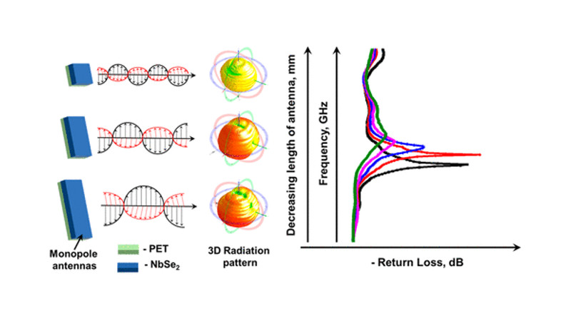
Researchers may have created the smallest-ever radio-frequency antennas, a development that should be of interest to any nanotechnology enthusiasts. A group of scientists from Korea published a paper in ACS Nano that details the fabrication of a two-dimensional radio-frequency antenna for wearable applications. Most antennas made from metallic materials like aluminum, cooper, or steel which are too thick to use for nanotechnology applications, even in the wearables space. The newly created antenna instead uses metallic niobium diselenide (NbSe2) to create a monopole patch RF antenna. Even with its sub-micrometer thickness (less than 1/100 the width of a strand of human hair), it functions effectively.
The metallic niobium atoms are sandwiched between two layers of selenium atoms to create the incredibly thin 2D composition. This was accomplished by spray-coating layers of the NbSe2 nanosheets onto a plastic substrate. A 10 mm x 10 mm patch of the material was able to perform with a 70.6% radiation efficiency, propagating RF signals in all directions. Changing the length of the antenna allowed its frequency to be tuned from 2.01-2.80 GHz, which includes the range required for Bluetooth and WiFi connectivity.
Within the ever-shrinking realm of sensors for wearable technologies, there is sure to be a place for tiny antennas as well.
[Thanks Qes for the tip!]


Wait, what does 10×10mm² mean exactly? Wouldn’t it be 4-dimensional?
No, since the first 10 doesn’t have a unit. But it should be in brackets for clarification. (10×10)mm^2
2.01 to 2.80 GHz which includes the range required for Bluetooth and WiFi connectivity
monopole antennas don’t exist. It is a misnomer (or a strange understanding of electrodynamics).
The typical stick antenna (lambda/4 radiator) of a portable radio is often called “monopole” to differentiate it from a (symmetrical) dipole antenna. Of course it is no true monopole, as it needs a ground plane or “counterweight” , e.g. the case and chassis of the receiver as a reference.
Mono meaning one, pole meaning a long, slender, rounded piece of wood or metal?
…and “antenna,” meaning a device that radiates (or receives) RF energy with a degree of efficiency. Essentially an antenna converts electrical energy in one dimension into an alternating electromagnetic field in three dimensions, and vice versa. An effective antenna needs to be a good electrical conductor, obviously. Wood is not a good electrical conductor, so a wooden pole would not qualify as an antenna any more than some other random shape, size and material would.
Without teaching an EE course here, a powered dipole (with a pair of 1/4 wave elements both driven) is the most efficient structure for converting AC electricity into EM RF fields, and vice versa. Magnetism has two poles, north and south. Electricity has two polarities, positive and negative. In the real world one doesn’t exist without the other. Some antenna designs conceal the second dipole element in the earth, the body of a car etc. This is called a ground plane antenna, and the asymmetry of the elements makes for a less efficient antenna. When the lower cost of the antenna and/or ergonomic benefits are of greater value than the lost efficiency, this is an acceptable trade-off. The fat remains that the second element is always there in one way or another.
“…it functions effectively.”
Maybe it does, but does it function efficiently? How many dB of loss compared to a dipole? How much power can it effectively transmit before the insulation breaks down? I’m sure there are many good questions to be asked of this thing, but I’m a radio amateur, not an RF engineer.
Any piece of conductive junk can be an “effective” antenna, but that doesn’t mean that it’s a GOOD antenna.
I suppose if it’s compared to no antenna it’s a 100% efficient antenna.
Using that metric, I would say that you are correct. :D
If you would take a moment to read the article you so expertly are commenting on, you’ll find the numbers you seek. (up to 70% efficient, up to 3.3 dBi gain, on a purported omnidirectional pattern.)
There’s a pretty high Bogosity Quotient on some other parts of the article though, so I question the credibility of those numbers.
Those numbers are unremarkable for a patch antenna. A “gain” of 3.3 dB relative to isotropic is just a fancy way of saying that the antenna can’t “see” more than half of the world around it. For an antenna design that purports to be omnidirectional, that’s not great.
The only real advantages of patch antennas is that they’re dirt cheap to make, and take up very little space, making them ideal for thin phone handsets. Make a thinner patch antenna, and phone makers can make their phones that much thinner and flimsier, so that many more teenagers will sit on their flimsy phones and break them. Win-win for handset makers, lose-lose for parents.
To be clear: There’s nothing magical here. These antennas are not nanoscale at all. They’re plain old patch antennas, of a size appropriate for their wavelength, but made with thinner conducting patch than is usual (sub-micron thick NbSe2 vs. the typical 1-oz copper plane, 35 microns thick, that most people would be happy with.)
They can be thin because the RF penetration
of skin depth is not so deep to be lossy at these
Frequencies but this is Stardard RF Microwave
Design 101 knowledge
Seems to the uninformed that words like
Nanometers is a big deal…. Funny
RF Microwave Design Engineer here !
The skin depth argument in the paper is specious and naive, and you shouldn’t be parroting their nonsense.
The whole thing looks like a Master’s degree project on how to deposit thin films, looking for a plausible application to justify it, and the authors really don’t know RF or antenna engineering very well. It shows.
And even more silly, the only return loss measurements they give are for the setup which includes an external copper ground plane about 10 times larger than the device itself. See page 4 fig 3c.
And to correct myself, that figure makes it plain that they aren’t constructing a true patch antenna at all (which requires its ground plane parallel to and under the patch). What they have is a scrap of conductor haphazardly tacked on the end of a coax. In HF and lower, we’d call that a capacitive top hat, only this implementation is rather clumsily executed.
it’s 10 x 10mm? That’s huge lol that’s 10 million nanometres, how is that nanoscale haha