Air conditioning compressors aren’t exactly a mainstay of the average hacker’s junk box. Typically, they’re either fitted to a car to do their original job, or they’re on the bench getting refurbished. However, with the right mods, it’s possible to turn one into a functioning internal combustion engine.
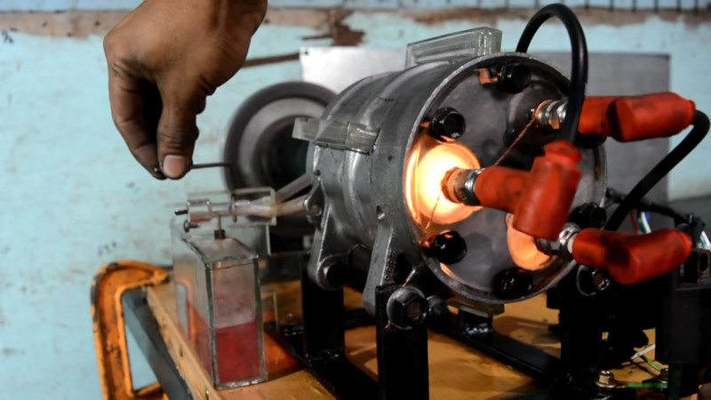
The build starts by disassembling the compressor, which contains three double-sided pistons. The housing is drilled with ports to allow gas to flow into and out of the cylinders, as well as to transfer from one side of the piston to the other. Acrylic end plates are fitted to the assembly. One end acts as an intake manifold, delivering air and fuel to the cylinders. The other side acts as the cylinder head, mounting the sparkplugs. Everything is then connected with acrylic tubing and a small square section of acrylic is turned into a carburetor to supply the air-fuel mix. Ignition is handled by coils triggered by the movement of the flywheel.
After an initial failure due to the acrylic manifold cracking, a stronger part is fabricated, and the engine bursts into life. The acrylic end caps give a great view of the combustion process in action. We’d love to see the a dyno graph on how much power and torque the unit puts out, or to see it hooked up to a bicycle or cart.
We’ve seen others attempt their own engine builds, too. If you’ve got an unconventional engine build of your own, be sure to let us know. Video after the break.


I seriously doubt that engine can run more than a minute or so without destroying itself since it has no cooling system. A similar mod was common, and much more practical, to make mini steam engines for solar collectors in the Mother Earth News era. Those could apparently be made somewhat more reliable, but are largely irrelevant now because solar panels have gotten so cheap.
I dunno, you can make much more efficient dynamos/generators now. You might be able to build more watts per unit area with those now.
I mean it’s a proof of concept, hence the acrylic. That stuff definitely isn’t gonna last, cooling or not. But i bet a system could be worked out with proper metal pieces. Might be able to simply submerge most of it in water, or machine channels for internal water cooling. But it’s basically valveless (at least on the side with combustion) so it really wouldn’t have a lot of vulnerable parts. You’d basically just need to figure out how to keep it from seizing.
“…valveless…” – it is a two-stroke design
Porsche used air cooling up to the early 90s
You are correct – But the problem is much worse than that! The load ratings of the connecting rods between the wobble plate, etc – That system was not designed for the extreme dF/dt you see with combustion – It was designed for a much softer curve as the result of compressing evaporated hcfc refrigerant. The compressor was designed for use in a zero-moisture environment, and any moisture will be very detrimental to the sliding surfaces of those pistons, and as we all should know, moisture is a byproduct of HC combustion – Big problem! There is also a major lubrication issue in general – In these systems, the refrigeration carries the lubricant oil, likely PAG 46 in this case.
There has been some success in use of automotive A/C compressors as engine-driven air compressors in off road applications, but for this to work the compressor needs a continuous PAG oil delivery on the incoming air stream and an oil separator on the output. PAG is not good for certain elastomers and since tires fit this description the use of a different lubrication oil is necessitated and in the end people tend to realize it’s better to just buy a 12V air compressor.
Connecting rods? What connecting rods? Those flattened single-ball bearings probably would need some improvement, that’s true. But also the action of these pistons is going to be much different because it uses a wobble plate instead of a crank. It’s significantly smoother on the reversal of direction. I imagine the compression ratio suffers for this, but not sure.
Also I assume one would use a two-stroke fuel and oil mixture on this since it’s very much a two-stroke engine. Still would need serious extra work for dependable, long-term use but I bet you’d be surprised just how much action you’d be able to get out of it if you replaced all the acrylic in this build with machined metal and did at least some attempt at cooling.
I honestly don’t know what the integral part between the piston faces that interfaces with the bearings is called when it is part of both pistons. My point is about the peak force, ie very high dF/dt which is far beyond the capabilities of this design and will rapidly result in what I believe would be multiple wear mechanisms – The high peak load of combustion will certainly brinnell the bearing race and will rapidly lead to spalling of the entire sliding surface. I would also expect a brittle type failure on the connecting piece/rod/whatever you want to call it between the pistons where it interfaces with the ball.
Two stroke oiling concept wouldn’t work without machining the pistons and adding rings like someone else mentioned… Custom rings that would be very pricey… And then you would need to sleeve the cylinders to prevent them from failing VERY rapidly!
Another big problem will be the short stroke of these pistons and angle of the wobble plate. You would need to go far beyond the design limits for rotational speed on this compressor to get meaningful power from it, and just the friction alone is going to destroy that poor little wobble plate with all the extra heat generated. I don’t see how any amount of work would be justified to get a little more life out of this thing when the design simply is the opposite of optimal for a swashplate style engine. To make it work you would be starting from scratch on a mill and building a completely new engine…
Don’t care how long it ran for, it ran!! bloody awesome little project and nice seeing someone working with minimal resources and equipment to achieve a goal.
1++
+2
Damn, that guy’s got some skills.
Yeah. Just machining ports with a hand drill. Amazed it works, pretty wild.
Having watched the full video, have to agree it is an awesome project even if it’s just a demo (it also has no long-term lubrication system, but DAYUM IT RAN). Particularly impressive that he did all the work with only handheld power tools and a drill press.
There’s a different model of A/C compressor that does have its own oil supply. The one in the video, as most modern ones, uses oil mixed with the refrigerant (or in this case, with the fuel, like a chainsaw, I guess), but old Fords and probably a few others (Jeep used the Motorcraft unit in the ’80s) up until at least the late ’80s had compressors with a separate oil system. They’re often used as air compressors, either on a stationary mount in the shop (I’ve used the one my grandfather attached to a washing machine motor in the ’70s to air up my car tires several times since I started driving in 1998) or nowadays under the hood of hardcore offroad vehicles, either with an additional belt and bracket or in place of the A/C, to adjust tire pressure in the field.
Just thinking, I might have an old chrysler one in the back shed.
What I’m more likely to do with it though, is see how much I can use it during engine braking to charge an accumulator (small tank basically) with exhaust gas. Then blow it all into the intake during next demand for acceleration. Lower pumping loss in part throttle acceleration and more gas for expansion. Hopefully resulting in better acceleration with less fuel use.
For this to be workable you would need lubricating oil, oil separator, some significant valving and control, and then in the end I would ask you what in the world you think blowing some extra air into your intake is going to do. If your vehicle is not already forced induction you are simply going to momentarily get some wonky MAP readings depending on control architecture and maybe a momentary lean condition… If it is already forced induction then you are just wasting your time. Do the math for the volume of air entering your intake even at idle and you will understand why. If you want a good laugh read about how chinese like to sell 12V squirrel cage blower motors on ebay as “electric superchargers” and find the forum posts from the silly buyers suffering the placebo effect on car forums… It is priceless!
If it was MAP it would go rich, MAF it might go lean if there was any O2 left in it, which I doubt. You seem to maybe halfass have an idea what you’re talking about.
You misunderstand. I asked what are you going to accomplish other than an anomalous MAP (or MAF depending on where you inject this air) reading and/or a lean condition if you are dumping a lot of air past MAF… Now I see…. You want to inject inert exhaust gas… To reduce pumping losses??? Please explain – I speak the language – My kess sits here waiting next remap for my commuter piece of crap car to get the curves right for the cheap bosch injectors that I regret picking, just finished resurfacing my heads on my own mill after pressing in new guides after porting the shit out of it to fit a different intake… I did airflow analysis on all of this… Have to swap heads in the cold side of the garage and winter is here…
I don’t have a crank grinder nor a decent boring bar yet. But someday….. Regardless of this you can take your “halfass” comment and change it to “fully” ;)
I really don’t like to insert my thoughts but,, Unfortunately for you pal you are the one that don’t know jack shit. In this world when you put your ideas out there you need to know what your talking about or be a damn good bull shitter. The guy you are arguing I honestly don’t know why he even wasted his time with you. You are not in the same league you got years of learning to do. I have no idea who he/she is but people like you are a buzz kill. You need to learn when your in over your head I hope your shit don’t discourage him from what he is trying to do. He has a good understanding. You don’t
I wrote a reply and it disappeared…
Didn’t notice you said “exhaust gases” – Please explain. I wouldn’t expect anything more than anomalous MAP/MAF reading from a burst of compressed air? MAP only for inert gas… Don’t see how you are going to affect pumping losses by blowing in some inert with the throttle plate open in an NA engine. You can talk the language, just finished yet another remap for my commuter piece of crap to optimize for these cheap bosch injectors that I had to buy… Kess faithfully awaits… Resurfaced my spare set of heads after pressing in new guides and cutting seats with serdi cutters (on the mill… no air table… it was painful…) and this after porting for the intake I am swapping in with new heads… I did airflow analysis on all of this with my poor-mans flow bench… I may not have a decent boring bar or a crank grinder but you can change your “halfass” comment to “fully” ;)
EGR works when it’s well set up https://en.wikipedia.org/wiki/Exhaust_gas_recirculation but first incarnations of it were a bit flaky so car guys tend towards a “rip it all out” attitude. However it can only do so much at certain operating conditions because there has to be sufficient exhaust pressure and sufficient intake suction. The pumping loss thing in that article is a little mis-stated because while normally it’s the vacuum from the throttle plate restriction pulling back on the piston, relieving vacuum between the two will result in less pumping loss without further opening the throttle plate. Anyway, plan is to extend conditions where EGR effective by having a reservoir of exhaust gas that was charged by recovering braking energy. I was mostly targetting under 3000 RPM and part throttle acceleration conditions. CFM requirements are 15% or less of what comes in at low RPM, part throttle. Doesn’t do anything for top end power, doesn’t do anything for midrange torque. Just meant to knock down your fuel eating by a few percent in stop-go when you have to go again after a stop. I’m working on a MAF vehicle. It doesn’t matter if it goes a bit lean, nothing bad happens, the EG buffers the bang so no detonation, it absorbs more energy into expansion without it heating up enough to make NOx, There is of course a crap load of details to work out, but valving and sensors can be repurposed from other applications. It may require piggybacking an AVR to trigger some timing sensitive parts. Hopefully that will be the same one that’s turning the clutch on and off for charging the reservoir.
Anyway, you can get your thinking really messed up by considering only that one line on a dyno graph which is only WOT performance, all the area under that is where most real driving happens. Then when you start the fuel economy discussion the “common knowledge” is mostly ass backwards. Then some Captain Thermodynamics shows up and says “But Thermodynamics!” without actually staying to listen about how you juggle kinetic energy, specific heat capacity etc to your advantage, often making the assumption that figures such as 35% efficiency for a gasoline engine happen all the time from the moment you turn the key to the moment you turn it off, and that the cycle cannot be modified.
RW, your concepts on EGR are outdated. There is no need for an extra reservoir of inert gas like this. If you wanted to do something like this you could simply modulate EGR valve signal as desired… You seem to think that there is an issue with a lack of exhaust gas for recirculation under some situations but that is not the case.
There are numerous engine architectures which use either use exhaust gas at many different engine RPM/load/etc conditions or control the stratification of the fuel/air mixture in the chamber. A good example is VW group’s FSI/TFSI engines. Stratified mixture of fuel/air in controlled volume in cylinder surrounded by leaner mixture. They achieve a non-homogeneous mixture in the combustion chamber (stratification) which if homogeneous would mathematically be extremely lean. Due to the stratification they achieve an optimized burn comparable or even equivalent to a homogeneous mixture with classic injection style. This concept removes the need to even have this inert gas – It is quite a cool concept.
Even without this, there are many different recirculation strategies which are using exhaust gas under various conditions to reduce fuel consumption and the end result is some of these otto cycle stratified engines reaching efficiencies previously unseen except for in extremely exotic(and costly!!!) applications.
If you were going to harvest braking energy to use in subsequent acceleration you would be much better off harvesting it as electrical energy, or hydraulic into some kind of accumulator, or even using boyle’s law to cool intake or intercooler to increase charge density on these hot components… But in the end you are not going to achieve anything past what is already being done. Engine architectures are incredibly optimized for efficiency right now. Best method is to harvest into electricity and slightly reduce demand on alternator… Hydraulic accumulators and intercooling have been explored by multiple US OEM over past 20 years.
Right, it’s mostly done through tight variable valve timing control now, but that is not really in the realm of garage tinkerer retrofitting.
Take the shaft, bearings and pistons from the compressor then toss everything else. Turn grooves in the pistons for rings. Weld up a steel engine block with three pipes for cylinders. Bore to just the right size for the pistons. Built inside a piece of well casing, there would be plenty of space for coolant. The center section would be isolated for the crankcase and you’d want an oil pump picking up oil from the bottom and squirting it onto the the wobble plate.
The one this guy built re-used the compressors reed valves. For longevity you’d want something better than that, like proper 2-stroke porting. What’s different about this build is it uses the opposing end of each piston to push the charge into the power side of each cylinder rather than using the crankcase like typical 2-stroke engines.
Even better would be to figure out a valvetrain or electric driven valving to make it a 6 cylinder 4-stroke. Might be able to fit a 4th piston and cylinder to make it a… WTH would one call this? Radial opposed? 8 cylinder.
Then mount it on a motorcycle or in a small car.
I’d like to have the 125cc 5 cylinder 4 stroke engine that Honda built back in the 1960’s!
https://www.motorcyclespecs.co.za/model/Racers/honda_125_fivecylinder.htm
Maybe something like this?
B^)
https://www.ch-ignitions.com/ums-125cc-gas-5-cylinder-radial-4-stroke-engine.html
Drill holes in all the cylinders just above the lowest point the piston goes. Put a spark plug on all six cylinders. Spray in fuel air mix via an atomiser next to each spark plug, perhaps even continuously. Do completely electronic timing.
Six cylinder, 3 set of opposed. Maybe even just use the drive shaft as a distributor and mount arms on the shaft that arc to the spark plugs.
I’d bet it lubricates just like any other two-stroke. Oil in the fuel. It even enters on a side of the piston with no combustion happening, so it gets plenty of opportunity to coat the cylinder walls and work its way up. Might need some kind of drip on the main bearings, though.
So he made a barrel engine, stay tuned for the DIY torpedo!
https://en.m.wikipedia.org/wiki/Axial_engine
This dude is a badass for sure. Wow. I remember hearing in auto class that some a/c compressors could technically be converted to engines but I’ve never see any one do it. Well done on this man.
I’ve never realized that carburetor is basicaly a venturi tube…
All these armchair experts decrying why it’s not a good idea – blah blah blah. It’s a proof of concept – an experiment – done for fun. I think this is great! I’m not saying this guy is the next Edison or Tesla, but as inventors go, they copped a lot of criticism from people who thought a “certain” way. I’m glad I’m not like that. Thanks for sharing HaD!
Yep, plenty of people who can do it better but none of them have done it. :)
On the contrary. It’s been done many times, it is a swashplate engine, and the same concepts and constraints that apply to those and other IC engines apply to this. There are a lot of common sense reasons that this won’t work, but that common sense comes from understanding of materials, engines, etc so I was not trying to pick on anyone. Before you plunge forward with a doomed concept like this, you should do a little research first. This is what engineers do. If you really want a working swashplate engine then just go buy one. They’ve even been tried in cars… Probably better than a wankel ;)
I found an ancient Youtube video of a barrel engine, apparently a VHS transfer. :O Just when you assume there’s no other way to X, someone points out another way to X. :)
https://www.youtube.com/watch?v=L3TIQ_YeBaU
Variable valve timing is generally used in conjunction with exhaust gas recirculation – Stratified injection is mostly airflow and injection timing/placement and you can make quite an excellent airflow bench at home. You don’t even need a microprocessor/microcontroller to do it. Very rudimentary concepts which simply require a good deal of studying beforehand and careful use of the scientific method. There are quite a few experiments you can do at home with variable valve timing! The key is to study first. Engines are not that complicated, the control strategies are what has become rather complex nowadays and these are quite proprietary in many cases and therefore poorly documented.
Just like a car alternator is an electric motor when wired up backwards, that type of A/C compressor is pretty much the same as the engine in, say, a Mk 48 torpedo. Well, the one in the torpedo is scaled up to fit in a 21-inch tube and makes 500 horsepower with monopropellant (no carburetor needed), but the moving bits are essentially the same — it’s a conveniently round package, to fit the application.