There are no shortage of CNC machines in the DIY space these days, but sometimes you just need to do things your own way. That’s what [Chris Borges] decided when he put together this rock-solid, concrete-filled CNC milling machine.
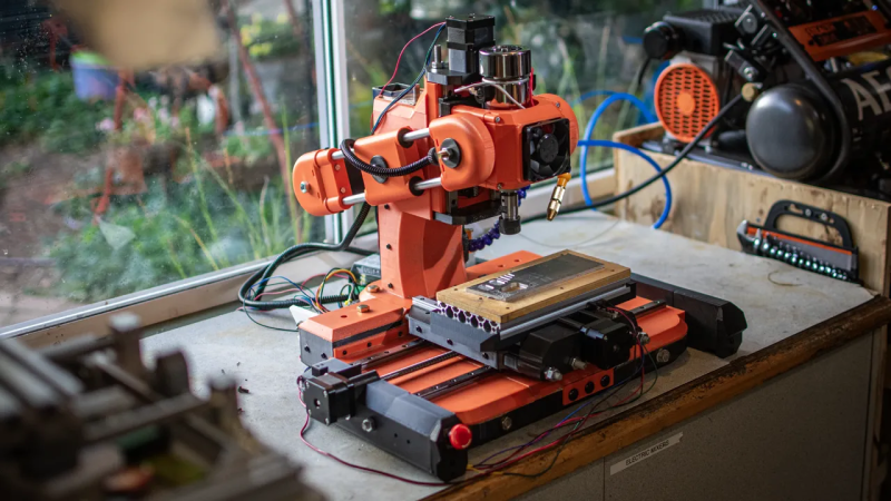
The concrete body of this machine is housed inside a 3D printed shell, which makes for an attractive skin as well as a handy mold. Within the concrete is a steel skeleton, with the ‘rebar’ being made of threaded rods and a length of square tubing to hold the main column. You can see the concrete being poured in around the rebar in the image, or watch it happen in the build video embedded below.
![An image of the main column of [Chris]'s CNC mill as the concrete is added. The steel reinforcement is clearly visible.](https://hackaday.com/wp-content/uploads/2025/04/pouring-concrete-mill.png?w=400)
Given that [Chris] has apparently never used a true mill before, this design came out remarkably well. Between the Bill of Materials and 45 page step-by-step assembly instructions, he’s also done a fantastic job documenting the build for anyone who wants to put one together for themselves.
This isn’t the first concrete-filled project we’ve highlighted from [Chris], you may remember seeing his lathe on these pages. It certainly isn’t the first CNC mill we’ve covered, either.


He seems to use a steel square tube, so the 3D printed part doesn’t seem to contribute much mechanically and is mostly aesthetic. The machine does look good though!
Your humour puzzles me. Chris does fine at presenting and sharing his projects as well as sharing his files like a typical hacker. Hard to ask more.
don’t worry little buddy, chatgpt can explain the joke to you
No gatekeeping. Dude made a good product.
This is cargo cult engineering.
Every mechanical interface here between the various parts and interfaces is made with plastic anchors sitting separately in the concrete, which does not make the structure rigid.
Usually when they make concrete pour frames for machines, they sink a metal anchor in the concrete. The metal anchor is what’s locating all the parts relative to each other and providing rigidity, while the concrete around it is adding mass and damping vibration. This is because the concrete is actually quite springy. It’s technically less stiff than aluminum (40 vs. 70 GPa) and all the rebar and stuff isn’t doing anything for that matter, because it’s like sticking nails into jello – relatively speaking.
All this is doing is making the machine heavier, which helps with vibration and surface quality, but the accuracy is not improved by the concrete because it’s still going to flex like crazy when you apply cutting forces. It’s still going to act like a CNC machine made out of cheese.
If you follow the path of forces from one part to another, you have a part bolted down with a steel screw in a steel nut (E=220 GPa), which is surrounded in plastic (E=2 GPa), surrounded in concrete (E=2-40 GPa), leading up to another plastic anchor (E=2 GPa), and then up another nut and a screw to whatever other part you have.
Those parts in the middle where the Elastic Modulus is low are acting like springs – especially the plastic around the nuts and screws – which makes everything move around when you apply forces. What’s the point of having a massive concrete slab for a frame if you’re going to attach everything to it with springs?
Well, it only has to be good enough. I’m sure the guy that made it will take your advice for the next revision, unless it’s working satisfactorily now.
Or, you could take the design and improve it! It would be an immense help to everyone if you iterated the design and updated the documentation. Looking forward to it already.
If I were to re-do this, I would start with an all steel “skeleton” where you have a plate of steel to mount the rails on, welded to box beams running up the tower, some sort of steel rods or beams running to the lead screw attachment points, likewise welded to the rest of the structure, and then 3D print just the outer covers to pour the concrete into. Every attachment point would be on steel, not concrete.
Nowhere that has to carry mechanical loads or precisely locate one part relative to another should there be metal-concrete-metal and especially not metal-plastic-concrete-plastic-metal, but directly metal-to-metal.
The idea of having a heavy cast base, but then making the carriage and lead screw nut holder out of plastic also completely negates the whole idea – although this can be improved later by simply replacing the carriage with a proper one. This is one of the weak spots where this whole thing turns to cargo-cult engineering if not addressed.
This has been done before, as seen on HaD if I remember correctly.
It’s really a chicken and egg problem. It’s hard to make a machine without a machine. Now that he has one, he can make the next one better…
These are all very good suggestions, some of which the jacket is aware of, others no so much. Why don’t you formalize it with some concrete patches to the design for the while community to benefit from?
The required information is available and easily picked up from Strength of Materials 101 and basic machine design textbooks. The most important parts are written down in the common reference handbooks for engineers. Writing it down again would be working for free and spoon-feeding people information they really should be looking for themselves if they intend to engineer stuff.
Now, I don’t know the background of this guy, but if they’re engineering a milling machine then they probably have the information at hand already – they’re just not applying it.
Oops, real work requested! Back pedal, back pedal!
I would expect this too, at engineeringaday.com.
What you’re asking from me is providing you a free course in mechanical engineering to the point where you can design a concrete base for a milling machine and evaluate its performance. Okay, but that’s going to take a while and you ain’t paying me anything. Meanwhile, if you just pick up the textbook, you can teach yourself just as easily without me being involved in any way.
If I merely “patch” the design, it doesn’t address the point of cargo cult engineering, because the people who receive the “correct” answer (it may not be correct for their case) will blindly copy it and introduce the same issues back.
Teaching trivial facts (or designs) to people who expect to be spoon-fed information is a pointless waste of everyone’s time.
They created a milling machine and posted their designs for free online for anyone else to modify and iterate on.
If you wanted to build your own milling machine they have already done an enormous amount of the work for you.
If you have an idea for how to improve it, thank them for giving you a baseline to work from, make the improvement, and share it back with everyone.
If you don’t have time for that, thank them for all the work they did, and kindly suggested how it can be improved.
Don’t be a gate keeping —hole who says ‘go and spend 4 years getting a mechanical engineering degree or don’t bother building anything’.
Dude it’s a kind of trolling…
Fairly common on hackaday.
Someone appears like a (well meaning middle schooler/MBA).
Proposing perpetual motion or making power from deep ocean pressure…
The kind of thing you expect from a bright 11 year old or 40 year old marketing major.
He argues with ‘Sorry won’t work, perpetual motion’ with ‘Explain to me why it won’t work’.
I don’t believe it’s even ‘good faith stupid’.
I think the troll laughs when some dweeb posts a wall of text attempting to spoon feed it to them (usually badly).
This is at least, sort of, not insane, pour ‘crete into it to stiffen it.
You can see where they’re coming from.
Also be aware:
‘Strength of Materials 101’ is usually 2nd year mechanical engineering track, for a prepared student.
It might as well be written in full tilt allegorical classical Greek for the marketer.
Ship has sailed, decades ago, perhaps the moment his dad…
Also no, the world is full of bad designs that ‘aren’t even wrong’.
They are not a good starting point for future work.
Especially something that’s as much a solved problem as a milling machine.
No they haven’t, because I’d have to design the whole thing from the ground up to fix their mistakes.
The basic theory can be understood on the level of high school math. It’s true that they like their Greek symbols though. The analytical solutions to complex cases turn hairy and require calculus to solve, but the simple stuff is not more difficult than using Ohm’s law.
The displacement of a structural member is always given by at least 3 variables, force, stiffness, and…. area moment of inertia! If you designed the entire thing out thin members, it doesn’t matter what material you select, it’s not going to hold up.
The advantage concrete has is that it’s cheap and has good stiffness. No other material can give you the same cross section for the price of a bag of concrete, which is why bulky structures often use concrete. You don’t need sheer stiffness if you can afford to make the thing big and fat.
1 mm of steel is worth 10 mm of concrete, depending on the concrete.
Which doesn’t answer Inund8’s point at all, as the 10mm and greater thickness of steel you’d have to buy and then machine to compare to a cast concrete structure that is many centimetres thick…. That is hundreds of dollars worth of raw steel, and you’d be turning lots of it into chips with lots of expensive machine time too, but ignore that for now, as just when compared to a few tens of dollars of mould material and a sack of concrete or two the price is already bad for the solid steel option.
Now a hybrid where you are using cheaper concrete or epoxy based solutions to add the mass to a thinner fabricated ‘sheet’ steel structure might hit that sweet spot of price to performance you are after, and if you still have a foundry you can hire (as home casting something machine tool sized is relatively implausible) cast Iron was the default for a good reason. But still it is hard to argue with the cheapness of concrete.
Yes it does. It gives you a sense of scale.
Given comparable cases, like making a beam out of concrete vs. steel box beam of the same dimensions, the steel can easily be ten times thinner. Remember that a grown man can stand on top of an empty soda can, as long as they don’t crush the sides in. In other words, even a fairly chunky slab of concrete may in certain cases perform just as well or poorly as a cookie tin. Concrete does not have “good stiffness” – you can tell that directly by looking at its Young’s Modulus.
This thing is far from ideal, but it’s not so bad as you claim.
First, with machines such as this mill, most of the flex comes from bending forces, and not from tension or compression. The concrete has most of the bending forces. Plastic between the steel rails and the concrete is also less severe. When the bolts are tight, they compress the plastic a bit, and the bolts also stretch a bit. The surface area of the plastic is quite big relative to the rest. So even though the plastic itself is not very stiff, it’s used in such a way that it does not matter much.
I also don’t agree that the rebar won’t help, (although it’s not in the ideal place). Steel is about 10x stiffer then concrete. I would like to see two layers of steel in the concrete, one at the top and one at the bottom.
But I agree this is a toy. It may be a quite usable toy, it can even be stiffer then the cheap 6040 gantry mills from China. Especially the version with the unsupported round guides are very bad. The better versions, with supported 15mm rails are better, but those cost around EUR 1200.
Also, in his video he talks about using the thing he built for real projects. I’m curious to see some more milling projects done on this mill. And then preferably with real sound (yeah, those things sound annoying, but the sound has a lot of clues concerning vibrations and spindle load.
If you want to build a real quality mill, then embed some soft steel flat bar into the conrete, then grind and scrape it flat after the concrete hardens and mount the rails on it. The cost for this are minimal, and you can build quite good machines this way. There are plenty of examples of this build method on youtube.
This is the worst part. The bolts don’t really stretch at all, since the elastic modulus of the plastic is around 1-2% of the bolt’s, so it’s the plastic that takes on nearly all of the deformation and stress. There’s basically no tension in the screws whatsoever, especially after the fact that the plastic will inevitably creep under load over time and lose the tension.
The attachment points in plastic are points where stress is concentrated in order to transmit it into the concrete, which makes it matter quite a lot. For example, the cutting forces sideways to the bed are shearing all the barely tensioned screws in their holes, sitting there like sticks in soft mud. If you try running a bigger spindle motor and increase feed speeds, the whole bed starts to wobble under the cutting forces and the concrete does nothing to help it.
I was not fully awake yesterday. Attempted to watch some details, and this mill is quite bad. The nuts themselves should be embedded in the concrete, but they appear not to be, and that is quite bad.
If you could tighten the bolts enough, there would be no shear force on the bolts, but sideways forces would be canceled by friction between the rails and the plastic, but as most plastics are prone to creep, the bolts would get looser over time, and this won’t work very well in the long term.
Another weird thing is the combination of concrete filled column, with a 40×40 square tube at the back.
Yet another part that is quite bad is how the forces go from the lead screw to the frame. This is a very weak piece of plastic, and not concrete filled. And this also easily deforms.
Using (money) coins as a counterweight is also not a “cost effective” method. Quite weird.
Everything put together, I agree that this is a quite bad design. You can make a good mill (VMC) form UHPC or epoxy granite, but this is not the way to do it.
That part makes the most sense, because the weight of the spindle motor is at the front, so the back beam is in tension while the concrete column is in compression. No problems there.
This is problematic because you can’t just embed the nuts into the concrete. You need some sort of flexible grouting around the nut and bolt or else the concrete will start to crumble. This is why the plastic around the nut sort-of makes sense, but at the same time it causes bad problems. This is why cast concrete machine bases employ a steel structure to actually carry the loads from one point to another, while the concrete is there to add mass and absorb vibrations.
And there as well, since you have an intermediate layer of plastic, even if the bolts were properly tight, the plastic is still what’s carrying the shear forces into the concrete.
Imagine if you had steel rails on a steel plate, but you had rubber pads under the rails. It’s a similar situation – the steel underneath doesn’t help much because the rubber is soft. To make it rigid, it needs to be steel against steel.
If the rebar isn’t connected to anything else, then it won’t really help with the main issue. You have to pass forces into the rebar through the concrete for it to have an effect.
Think of a steel bar inside a pool noodle. Sure, it’s stiff to bend, but only once you compress the plastic foam around it to have a grip on the steel bar inside. If the point is that the foam noodle is supposed to maintain its shape, then the steel bar didn’t help.
Also, out of curiosity, how would you describe a bending force as it manifest as stress in a part that is being bent?
Tension has pretty much the same stress across it’s whole surface. Think of a tightened bolt. With a banding force, you have compression on one side, and tension on the other side. The difference is extreme with a steel cable. pulling on the cable will not stretch it much, but bending the cable is very easy.
Construction parts which have bending forces should also have a lot of thickness. The bottom concrete is now approximately a 50mm thick concrete slab. Using two 20mm concrete slabs with a few cm of air (polystyrene foam during casting) gives it a lot more stiffness for the same weight.
For tension or compression, the material properties and it’s cross section (i.e. how much material there is) is the dominating factor, while for bending forces, the distance of the material from the centerline is very important.
A solid rod with a diameter of 12mm has the same cross section as a 20mm tube with a wall thickness of 2mm. In tension, both will deform equal under the same load. When a bending force is applied however, the tube bends a lot less then the solid rod. Because of this, milling machines are usually made of hollow cast profiles, and it’s also why UNP and H profiles are used in construction.
The point was that bending loads ARE tension and compression. The cases aren’t fundamentally different.
And using two steel sheets of about 1 mm thickness with 20 mm of foam in the middle would likely outperform it on all accounts. Especially for the fact that the concrete does not fair well in tension (it breaks).
I’m not a mechanical engineer. I’m currently waiting for concrete to dry as I made a concrete shelf for my 3D printer to sit on. The reason I went for reinforced concrete is because a steel plate, although much easier to work with, would have been much too springy to set a 3D printer on. It’s currently sitting on my large dining room table and when printing, the entire table shakes. The mass of the concrete doesn’t allow vibrations to get through unlike steel plate, which acts like jelly. Removing the vibrations from steel is a struggle. Got a vehicle that I covered on the inside with as much rubber as I could, to dampen it as it would otherwise just shake itself apart.
Granite counter top remnant makes a helluva machine base.
That’s the point of concrete cast bases.
But the steel does not act like jelly – the concrete does – and that is why the concrete is good at absorbing vibrations while the steel passes it right through. In more technical terms, there is a mechanical impedance mismatch between the materials which reflects vibrations at the boundary, not letting them pass through, and then as the concrete is soft relative to the steel and made of hard sand granules embedded in flexible cement (again, impedance mismatches and lots of internal reflections from boundaries), it absorbs the vibrations better. A vibration shock going through the concrete gets dispersed quickly into many tiny vibrations, and then absorbed into the vibrations of the sand granules, which ultimately consume it to heat.
Coincidentally, this is why cast iron is better at absorbing vibration. Cast iron often has graphite nodules and distinct grains of iron inside, while steel usually has a smaller and more uniform grain structure with the carbon dissolved all over the place. The harder the steel, the more uniform the structure, and the better it “rings” with vibrations. The coarser structure of harder materials suspended in soft iron gives cast iron the same ability of dispersing and absorbing mechanical vibrations.
yeah this made me deeply uncomfortable. it’s like in the uncanny valley of good ideas where it incorporates so many elements of good ideas that you can’t believe how clear it is on first inspection that it’s a bad idea.
i’m all about using 3d printed parts as just essentially brackets to orient add-ons, and the strength comes from the add-ons. i’m just super skeptical of the idea that concrete is the answer.
i mean it really depends on a lot of variables. maybe this will provide decades of valuable service. i just want a composite to inspire the thought “oh, this is getting the strengths of both materials and the weaknesses of neither”. and concrete+plastic doesn’t give me that feeling. concrete is so heavy that its proximity to the plastic inevitably kills the plastic, i’ve seen that happen too many times.
Indeed, the actual concept of a 3d printed former for your casting concrete/epoxy system is good, some of the other design options used are interesting but the execution in this case isn’t great as its leaving plastic in all the wrong spots still…
You can tell from the guy’s previous video where he made the concrete cast lathe that he doesn’t really know what he’s doing. He’s “vibe-engineering”.
He put a plastic sleeve around the main bearings, and then someone in the comments said “You should put a lock nut on the shaft so you can apply a preload on the bearings”. Wait? So they didn’t even pre-load the tapered bearings? How is it going to be accurate if the bearings are set in plastic, and then not even tightened down?
The entire point of the concrete cast is lost on little details like that.
Due to how often we see 3d printing misused, the knee jerk reaction should be somewhere between pitchforks and a mild eye-roll.
But in this specific case it might, MIGHT, actually be a good way to achieve the desired results.
This appears to be using 3d printing as a simple way to stiffen and beautify a machine built in a more traditional way. Which is a good use.
However, if you are already doing the work to build the actual mechanical portion traditionally…why go through the extra steps to use a different method instead of just building it stiffer in the first step?
In the end, you get a usable machine, but you did more work to get there.
You also made more waste.
There will be times that it still makes good sense to do things this way, so knowing it CAN be done is valuable. But, just like everything else 3d printing related, it is still probably the wrong way to do it.
I love that this guy is just going solo down his own technological path, and making more and more progress. Awesome work!
Exactly.
For all the people critical of using printing here, you have a valid point, but there’s an easy way to fox plastic on the interface.
What you do is leave an open face on the printed part where something needing rigidity will bolt to it, and then place a piece of flat material over the hole when you case the concrete. Then you de-mold the part, and you have a much more solid face. You also want to anchor the anchors deeper into the concrete to spread out forces better.
Basically you use 3d printing like he does for all the complex geometry, and leave the critical faces open to cast with more traditional mold techniques. You can get quite decient parts this way. You can also embed steel plates at the surface using similar techniques.
I’ve built a small cnc mill using this technique, and it works quite well. Only difference was I used an epoxy based fill and numerous steel inserts. (But concrete can also give good results if it’s the right formulation. Needs to be a no/low shrink mix though, off the shelf concrete will shrink by several percent while curing. Look into grout for ideas)
You can also cast against a reference surface if you want a precisely flat surface, a surface plate works great for this. Makes it easy to cast flat and parallel rail mounting surfaces into a part, no grinding / scraping needed. I’ve found what works best here is a steel bar, etched in strong acid to take the mill scale off, epoxied down to the surface plate (wax the plate first lol). You get a very thin film of epoxy that flattens the surface out, but is so thin it doesn’t impact the rigidity, and your bolts tap directly into a piece of solid steel.
I would like to see some pictures of your method
At some point I’ll probably do a writeup; my current machiene is kinda a cobbled together mess of experimental techniques, so I’m not sure if it’s all a great example. Some parts of it are I guess lol.
At some point I might rebuild it / build a second machiene; ill probably do a writeup at that point
imo it may be the best example because it sounds like it’s used and someone has battled its flaws for a while!
Yes indeed, this is a good method.
Similarly I’ve also seen concrete poured into a mould, and painted with an epoxy paint after demoulding. The contact surfaces get an extra layer of epoxy paint, and then the paint is sanded, ground or scraped flat before mounting the rails.
Id prefer epoxy bonded granite powder to concrete but otherwise, pretty cool.
It really does not matter much whether you use epoxy or UHPC. Epoxy is probably stronger, but the strength is not the defining factor here, especially when you put in some rebar (I.e, Youngs modules of steel is approximately 10x that of concrete). And UHPC is a lot cheaper then epoxy.
Also, Basalt is a good alternative to granite granulate. Basalt is also often easy to obtain, as it’s also one of the decorative rock types commonly sold for garden paths and such. Basalt also has a (slighlty) higher density as other rock types, and with that it’s also a bit stiffer.
Epoxy bonded granite powder only uses 10-15% epoxy, so its certainly not breaking anyones bank EBG is fully hardened and cured within a few days, Under ambient conditions, Ultra-High Performance Concrete (UHPC) may take up to 28 days to fully cure but can take several years for its moisture content to stabilize resulting in potential dimensional instability developing over time. EBG also has superior vibration dampening properties compared with concrete.
Theres a reason Fadal, Haas, Mazak, DMG Mori, Okuma, and Makino as well as other professional CNC manufacturers use EBG over the other options in their machines constructions.
If the measure is the USD $300 price point then it’s pretty dang good.
Although he will run into size problems really quickly. But on the other hand it seems like price of these mills increases exponentially with Y size.
I think that if you grab the collet nut and give it a good yank and it doesn’t move then you’ve done well. Also if you make an aluminum part and look at the chatter marks that’s a good indicator.
Some may be familiar with the Taig Micro Lathe and milling machine. The bed of each is filled with portland cement (not concrete) which provides significant mass and dampening.
I’m astonished by the destructive criticism here. It’s really good baseline criticism, but there is zero gains for putting a destructive spin on it. We’re all hackers here. Play nice.
Only Sith deal in absolutes….
And I see a lot of absolutes being thrown about in the comments.
So let’s get relative: Is or is not the stiffness of the concrete greater than the flexure of the 1/8th inch endmill (or thereabouts) that he’s using for cutting?
From the video of him milling the brackets for his limit switches, I’d say it is. Look at the surface finish on the bottom of that trench. Looks like flippin liquid. Nuff said.
Even if your rig is made out of Adamantium, or Uru, or Mithril and doesn’t flex at all, your tooling is still going to flex some, so in the end, it all comes down to what the rig is designed to do. If it’s designed to cut up to mild steel and it accomplishes that task, then that’s fine. If it’s designed to cut up to aluminum or brass, then that’s fine, too. The guy in the video doesn’t seem to be interested in cutting tight tolerances in Inconel, so he made a machine that stops short of that for less money.
great observation. instead of writing a dissertation on how the materials behave theoretically, you cut to the chase and say, “see, it slices cheese”.
The point is, even a fairly feeble mill will cut bog standard aluminum just fine, because the material isn’t that demanding. If you mind your feeds and speeds, it’s going to make good results even if your mill was made out of cheese.
If your argument is that the tooling is the limiting factor, that’s a point of diminishing returns. Putting a lot of cargo-cult engineering into making a “better” mill just to cut the same aluminum at the same feeds and speeds is not going to improve your results, so you can’t tell whether you’ve made it. How then do you justify the effort?
The tragedy is that people mistake effort for value, so something needlessly complicated or laborious is judged as better by default if you don’t take a closer look at what’s actually being done.
Thumbnail looks so good it seems ai generated hah buy i know its not bevauee I’ve followed this creator
Oh and to the detractors ….how ELSE would you make your own milling machine? The point is the 3d printing let’s you assemble it from scratch even if you still need the metal parts …those are commonly available and some of us alrrady have rods. And yeah concrete and printed parts or what? Wood? Hah how else do u make it yourself withiut a 3d printer? Metal parts? Made with a cnc machine?
I mean the point here is you CAN convert cheap concrete and maybe even cheaper (IF you made your own filament and got good at recycling bottles) filament and scavenged parts to make a DIY milling machine. These are probably the cheapest materials. Unless you think you can use wood and treat the wood somehow with resin or something? I think 3d printed with concrete with the right design is gonna last forever if u design it right
Most if not all the detractors are not about using 3d printing at all, its about where the plastic is used and how much of it is kept into the final machine – there is just too much plastic in parts of the functional structure where you really should want all the functional stuff to be directly attacked to the concrete or the embedded steel in the concrete.
You could use almost this exact method and get a much better result if you made sure to use the plastic just as a former for the casting that allows you hold all the hardware to embed in the concrete/epoxy granite pour in place. You could if you like keep the plastic in the less important functional bits like the counterweight and retain it as the outer shell as long as the essential motion works are bolted straight to the concrete/steel embedded in it without that plastic that will creep under the clamping load so the bolts get loose, allow for more flex as its just a more elastic material etc.
All that said this machine is probably going to be pretty darn good in use because its really quite small and can’t take larger cutting tools – it is only as you scale up the machine or tool sizes so the leverage of the cutting forces and inertia of its own mass start to really get large that I’d expect a construction like this to really be a problem.
note I meant “darn good in use FOR THE PRICE”
Scrap pieces of aluminum extrusion table plates don’t cost a whole lot – just dollars per pound – and it’s going to be stiffer than the concrete and plastic for a similar size of a bed plate. Go to your local metal recycling company and ask them, or any company that sells the extrusions. They usually keep a pile of random chunks and off-cuts for people who come asking.