We generally cast a skeptical eye at projects that claim some kind of superlative. If you go on about the “World’s Smallest” widget, the chances are pretty good that someone will point to a yet smaller version of the same thing. But in the case of what’s touted as “The world’s smallest vector monitor”, we’re willing to take that chance.
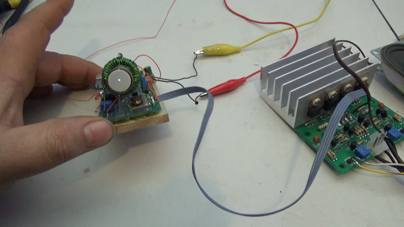
If you’ve seen any of [Arcade Jason]’s projects before, you’ll no doubt have noticed his abiding affection for vector displays. We’re OK with that; after all, many of the best machines from the Golden Age of arcade games such as Asteroids and Tempest were based on vector graphics. None so small as the current work, though, based as it is on the CRT from an old camcorder’s viewfinder. The tube appears to be about 3/4″ (19 mm) in diameter, and while it still had some of its original circuitry, the deflection coils had to be removed. In their place, [Jason] used a ferrite toroid with two windings, one for vertical and one for horizontal. Those were driven directly by a two-channel push-pull audio amplifier to make patterns on the screen. Skip to 15:30 in the video below to see the display playing [Jerobeam Fenderson]’s “Oscilloscope Music”.
As much as we’d love to see a tiny game of Battlezone played on the diminutive display, there’s only so much it can do. Maybe an analog version of this adorable digital oscilloscope would be possible?


But the video is not at home.
The circuit diagram he draws doesn’t make sense. The output of the inverter is either active low or high, so whatever is happening with the first potentiometer giving out 10 Volts is irrelevant – it’s overridden both ways by introducing the voltage from the inverter to the wiper of the second potentiometer.
If it makes any difference at all in practice, it’s not by design but because there’s some output impedance with the inverter and a contact resistance in the second pot, which means the circuit does not function as drawn.
Well that’s generally the point of contrast and brightness controls, you want to override the input signal and make it brighter or darker according to the bias of the voltages.
Yes, but in this case the signal from the inverter would, if the circuit is drawn correctly, override it entirely.
You can think of the potentiometer as two resistors in series. Let’s call them Left and Right. When you connect a voltage supply in the middle, anything connected to the other end of the right resistor cannot see what happens at the other end of the left resistor, because the voltage in the middle is fixed. Any current flowing through L is independent of any current flowing through R.
Now, in the case of the inverter, the voltage in the middle is fixed at either Vcc or ground, so at all times whatever happens with the “brightness” adjustment cannot affect the current at the electron gun. The circuit just doesn’t work unless there’s something else going on that was omitted.
Didn’t he explain in the video right after he mentions using the inverter that contrary to popular belief they are not perfectly binary devices and will attenuate the output based on the input until it reaches the state where it switches the output to the grounded state? At least, that’s what I got out of it.
Yes, he described the switch-over process, but in this state the output functions as a linear amplifier – still a voltage source – and the issue still remains.
What’s really happening is, he’s probably using the asymmetric features of the inverter chip to perform the mixing function. It has nothing to do with the switchover state or anything, but the fact that the actual inverter chip cannot source as much current as it can sink, so it does not act as an ideal voltage source while the output is high:
http://www.bristolblog.com/ele/images/7404.jpg
Of course, if the potentiometer has a high value like 10-100k then the output resistance of the inverter may still be small in comparison, and the effect would be the same – the current coming from the other potentiometer wouldn’t really matter.
The output will float if it’s not actually tied to ground, right?
The old National linear data books had sections on using CMOS inverters as linear amplifiers with feedback and other things similar to an op-amp.
I saw that and just assumed the inverter was open collector/drain. That way it either grounds the signal or leaves it as is
Yes, but as long as it’s not specified, it’s “an inverter” without any other information, and if you’d try to simulate the circuit it wouldn’t work, and if you tried to build the circuit without accidentally using the same part, it might not work.
Here’s the 1970’s take on it: http://www.ricomputermuseum.org/Home/test-equipment/nls-ms-230-oscilloscope
I wanted one of those “so bad” back in the day!
It would make playing Red Baron an adventure….
Seems like an awfully painful way to make an inefficient deflection coil. I wonder why he didn’t use ordinary saddle coils?
Whoa, never seen a round-screen viewfinder CRT. I collect a few of those, but they’re all square. I love the round ones. I want it.
I would have assumed most of them were round. at that size it is probably the easiest shape to work with, and you really aren’t all that worried about wasting a bunch of materials. Just underscan the rectangular image so it fits in the circle and mask out the rest of the screen in the enclosure.
You’ll probably have to hit up yard sales for a Betamax or early VHS camcorder the size of a ground to air missile launcher then.
I understand being concerned about burning the phosphor, but honestly, as long as you keep the brightness low, it’s not a hazard, and certainly not for the time it would have taken to shoot this video. Annoying as hell, watching a severely out of focus demo. I suspect he actually couldn’t get it to focus.
Your sorta right the only way I can get it to have a sharp focus is to raise the brightness to a VERY high level. Normally this would have been ok but not in this case.
Perhaps the 3mm CRT display (scroll down to view) qualifies?
http://www.sparkbangbuzz.com/crt/crt6.htm
I’ve seen this guy’s work before, but not the 3mm one. It’s kind of inspiring. Cold-cathode CRTs, no high vacuum needed. I’m thinking CRT clock, now. Not 3mm, though.
Or how about cold-cathode beam-steering logic elements? Lots of transistor and relay computers have an LED connected to each gate or flip-flop, but beam-steered gates would have built-in indicators. Maybe even a different phosphor color for the 1 state than the 0.
I am wondering how much X-ray radiation this type of tube produced, entering your eye (when used in a camcorder back in the day) and straight through into your brain?
Sony got sued once but they won