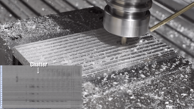
When you’re operating a machine that’s powerful enough to tear a solid metal block to shards, it pays to be attentive to details. The angular momentum of the spindle of a modern CNC machine can be trouble if it gets unleashed the wrong way, which is why generations of machinists have developed an ear for the telltale sign of impending doom: chatter.
To help develop that ear, [Zachary Tong] did a spectral analysis of the sounds of his new CNC machine during its “first chip” outing. The benchtop machine is no slouch – an Avid Pro 2436 with a 3 hp S30C tool-changing spindle. But like any benchtop machine, it lacks the sheer mass needed to reduce vibration, and tool chatter can be a problem.
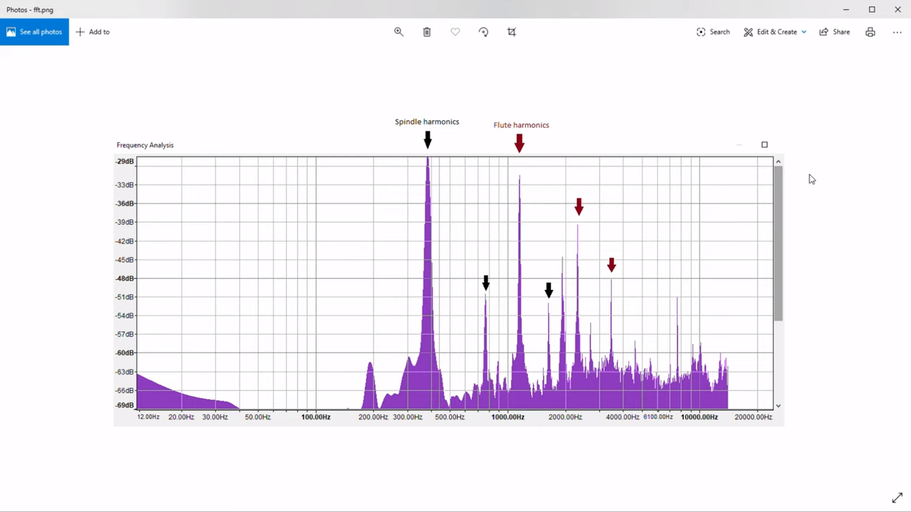 The analysis begins at about the 5:13 mark in the video below, where [Zach] fed the soundtrack of his video into Audacity. Switching from waveform to spectrogram mode, he was able to identify a strong signal at about 5,000 Hz, corresponding to the spindle coming up to speed. The white noise of the mist cooling system was clearly visible too, as were harmonic vibrations up and down the spectrum. Most interesting, though, was the slight dip in frequency during the cut, indicating loading on the spindle. [Zach] then analyzed the data from the cut in the frequency domain and found the expected spindle harmonics, as well the harmonics from the three flutes on the tool. Mixed in among these were spikes indicating chatter – nothing major, but still enough to measure.
Audacity has turned out to be an incredibly useful tool with a broad range of applications. Whether it be finding bats, dumping ROMs, detecting lightning strikes, or cloning remote controls, Audacity is often the hacker’s tool of choice.


Awesome technique. People often overlook sounds as an analytical tool. I’ve used sound to determine RPM on a number of occasions – whip out my phone, hold a piece of paper against a spinning part (as long as it has some surface detail to catch the paper periodically) and record a few seconds. Easy enough to work out a reasonably accurate RPM by looking at the wave form.
Nice technique!
Thanks for sharing.
I used to connect headphones to circuits and hold a mic up to them for the world’s crappiest isolated oscilloscope. Now I have a real handheld scope, but you’d be surprised how useful just knowing if there’s high frequency change happening or not can be.
There’s actually an app calle Giri that can estimate RPM by sound. Works decently
I have an app called Girlie, but it doesn’t do that!
Harmonic analysis is routinely used by spindle manufacturers and rebuilders as part of their QA processes, and in the case of a rebuild, often performed before the rebuild too. Every system has natural frequencies that cause resonance, and running a CNC machine close to one of its natural frequencies will result in poor surface finishes and diminished tool-life due to chatter at best, with broken tool bits and scrapped parts a possibility. Spindle bearing life can also be severely impacted, resulting in costly rebuilds and machine downtime.
If the problematic frequency is one of the spindle assembly, then tweaking the spindle speed is usually the solution. If it is from one of the linear motion components, then tweaking the feed rate should take care of it. Some vendors now are selling systems that can integrate with the control to automatically do this in real-time. This is fairly new in the field, in the past decade or so. Dare I say it’s cutting edge?
Interesting. Totally cutting edge. :-|)
Great article and comment(s).
I do recall in another Hackaday article (though forget which), a comment regarding race car crews/teams for decades having someone that would perform the acoustic analysis to study operating parameters of the competitions vehicles, and their own I guess, to determine parameters and I guess optimize performance.
I’m aware also of the automotive industry, or at least contractors, performing resonance testing to determine rigidity or whatever the mechanical specifications (compression, tension, torsion, flexion, etc.) are that related to stiffness of the chassis or frame.
I recall and engineer or two also noting how in general the noise from a vehicle changes from stock low mileage to higher mileage and after an accident.
Then of course there is the in general damping of the sound on the interior of the vehicle studies in more recent years.
Can this be used for automated real time monitoring and possible shut down a machine to prevent catastrophic failures?
Theoretically I bet it could! Most of the research however (at least from what I’ve seen) is in regards to adjusting cutting parameters in real-time, or using some kind of active compensation method (transducers on the spindle or workpiece), with the goal of eliminating chatter.
But there’s no reason acoustic profiles couldn’t be associated with catastrophic events. Some things will always be hard to catch because of the speed, like a rapid plunge into the vise jaws or something. But if you consider that slotting operation that welded, there was a _long_ runup of bad-sounding acoustics which easily could have triggered an abort rather than just adjusting parameters.
linuxcnc has hooks for changing the feed rates as a function of some other variable, specifically for adaptive feedrates, but it would be easy to hook up a hardware abstraction layer component to the output of this to make it either slow or stop entirely.
Now that is useful info. Didn’t know you used that software.
This overall is an excellent article, and a highly neglected but very interesting subject.
For the record, while most machining should be fairly quiet if you are doing it correctly, what I do for my day job is loud by nature, as I hardmill hardened H13 toolsteel in high 40s rockwell. It naturally is a loud operation even when you are doing it right, from what I’ve found, much more so than standard good machining.
There are commercial products that do this to detect broken tools.
Very interesting. I sometimes use this technique on a smartphone to assess grinder rpms or my boat motor rpm. I’m not so sure, however, that getting a 3 HP spindle on such a cheese mill was a wise idea. Needlessly heavy and impedes the dynmic performance. The aluminum surface looks atrocious, just as one would expect with such aggressive feeds.
A 3hp (2.2kW) spindle is the same caliber that Avid sells for their routers, including their Benchtop models: http://www.cncrouterparts.com/22-kw-plug-and-play-spindle-vfd-system-p-353.html
I was purposefully pushing the feeds to see what the upper end of the machine is, on a battered and old end mill no less. For fine surface finish I think it’s pretty obvious a gantry router will need to bring down the feed for finishing passes. I’ll be doing testing of that in the future to find a good recipe, but I was interested in seeing how much material could be hogged out as the first test. No good reason really, just because that was more fun :)
Cool! Did you do a power calculation? I was fairly surprised when I calculated the numbers for my typical jobs. It was all just a few Watts, seldom even over 100 W.
Sorta. The horizontal test cuts all had calculated horsepower (listed in the text below the cut), and maxed out around 1.8hp (1.3kW). Unsure how much was being used in the pocketing operations. The speeds/feeds were configured to hit around 1.3’ish (950W) but not sure in reality since I don’t have a spindle load meter. Although that is one of the my future todo’s: see if I can wire the VFD to send wattage or current back to the Avid system so I can display it in Mach :)
I assume that these readings are from an acoustic mic near the tool piece. An electret mic used as a contact mic on the spindle head or on the work might be more revealing.
Audacity in the wasapi mode (not wasabi) is a very cool way to audit your or anyone’s video or streamed radio volume level. Bit to bit, no analog stuff in the soundcard. When activated (it’s the left most drop-down) it records the audio with no volume controls to interfere with the absolute digital signal. Highlight the sample (double click) of audio and then select effects—amplify, it will show how many dB it needs to raise the level to achieve normal full level. You will know how much to turn it up and then post it again. This video has good volume, within 3 dB.
Correct, the recording was from a dynamic shotgun mic that I use with my camera (so decent quality, but nothing to write home about). I have a much nicer condenser mic that I might drag out to the garage to get better acoustic readings.
++ to sensors on the spindle or machine frame itself! The literature has a lot of neat examples of this. Either mics as you mentioned, or accelerometers or force transducers. Combined with current draw from all the motors and the position in the toolpath there is a _huge_ opportunity to optimize (albeit very difficult).
Machining tends fix problems by more mass, more horsepower, more speed, more rigidity, better cutter geometry, etc. But from what I’ve read many of those gains are starting to diminish as some have been scaled to their practical limits. So research is starting to shift to intelligently configuring toolpaths at runtime, which is super neat to me :)
Will check out the wasapi mode, thanks for the tip!
Holy eye protection Batman!
Would be super cool to be able to add something like this that would provide feedback and alter the speeds and feeds dynamical as the tool wear takes place. Even better for protecting really fine milling bits.
I’ve been in the industry for 32 years . When it comes to any type off CNC machining , you most definately need to have exelent hearing ability. Colin.
I think the chatter analysis really reinforced to me how finely tuned machinist’s ears are :) It’s impressive really how much information is transferred through the acoustics, and that machinists intuitively use that information to adjust in real time. I hope to someday have an ear for that too!
Being an experienced cnc operator who does all of production design; I can tell you with utmost confidence that sound is everything..working on the computer in an office 75 yards away from an axyz 6×12 with 12 hp or even an inferior machine,…I could tell the operator was not running my parameters as I had set them and would run to the machine to adjust it.. its blatantly obvious..that amateur stuff people..
What Had content is “woke”?
Or “postmodern”?
Not so much of the content, but “non-woke” comments often get deleted.
This was (is) an active area of research for mechanical engineering.
If you’re interested in the mathematics of what is actually going on check out “Frequency Response to Improved Productivity” by Dr Scott Smith. You can actually predict the harmonics of a cutter and machine by characterizing the machine’s frequency response you can then pick the ideal cutting parameters.
Here is a practical demonstration of the technology: https://youtu.be/uv3yUCl27wM
What isn’t shown is the characterization of the machine. It’s rather simple, attach an accelerometer to the cutting tool (literally just wax that holds it), then tap it with a small instrumented hammer (the hammer also has an accelerometer). The frequency response of the machine and tool is then fed into the system to determine the ideal stability lobes for the equipment and cutting tool.
Very brilliant stuff, but it’s very expensive for the hobbyist ~$10k just for the kit to analyze, not including software. It’s main use is in aerospace for machining large parts quickly and very thin walls quickly.
With audacity, a mic or transducer and a small hammer to ring the tool you can do much of what the setup shows but without the ease of the software. Record the vibration of the tool when struck and use FFT to see the peaks. Pick the strongest peak freq. * number of flutes and set your RPM to a multiple of that or just below it to stay in the stability zone. The basic idea is to have the tool/part vibration match and keep a constant chip thickness. This keeps the part from self exciting and the load on the cutter constant.
People like you are the reason I come here.
The basis of this is over a decade old, but it is a complex topic. Partly because the CNC machine, tool and part make up a combined complex system of parts all with natural frequencies.
A quick google search came up with this PDF paper https://www.mdpi.com/1996-1944/12/19/3193/pdf An interesting part is the stability zones and how there are specific spots to find more stable cutting parameters.
Hass actually puts out lots of useful tutorial videos to get people started on many topics. https://www.youtube.com/watch?v=rKPxfzx3sxE and https://www.youtube.com/watch?v=dXR2wDDFFm4
Some higher end machines now have vibration sensors on the machine, and even on the tools that are monitored and can adjust speeds and feeds to eliminate chatter or detect broken tools.
Okay guys!
Cut the chatter and get back to work!
That is legitimately cool.