A Simple App Controlled Door Lock

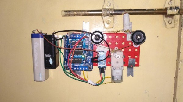
[Adnan.R.Khan] had a sliding door latch plus an Arduino, and hacked together this cool but simple app controlled door lock.

Mechanically the lock consists of a Solarbotics GM3 motor, some Meccano, and a servo arm. A string is tied between two pulleys and looped around the slide of a barrel latch. When the motor moves back and forth it’s enough to slide the lock in and out. Electronically an Arduino and a Bluetooth module provide the electronics. The system runs from a 9V battery, and we’re interested to know whether there were any tricks pulled to make the battery last.

The system’s software is a simple program built in MIT App Inventor. Still, it’s pretty cool that you can get functionally close to a production product with parts that are very much lying around. It also makes us think of maybe keeping our childhood Meccano sets a little closer to the bench!

These Bit Twiddling Tricks Will Make Your Coworkers Hate You

In the embedded world, twiddling a few bits is expected behavior. Firmware is far enough down the stack that the author may care about the number of bits and bytes used, or needs to work with registers directly to make the machine dance. Usually these operations are confined to the typical shifting and masking but sometimes a problem calls for more exotic solutions. If you need to descend down these dark depths you invariably come across the classic Bit Twiddling Hacks collected by [Sean Eron Anderson]. Here be dragons.

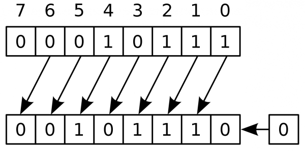
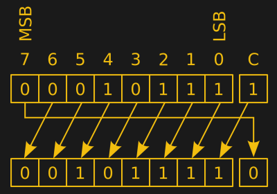
Discussions of bit math are great opportunities to revisit Wikipedia’s superb illustrations

Bit Twiddling Hacks is exactly as described; a page full of snippets and suggestions for how to perform all manner of bit math in convenient or efficient ways. To our surprise upon reading the disclaimer at the top of the page, [Sean] observes that so many people have used the contents of the page that it’s effectively all been thoroughly tested. Considering how esoteric some of the snippets are we’d love to know how the darkest corners found use.

The page contains a variety of nifty tricks. Interview content like counting set bits makes an early appearance.  There’s more esoteric content like this trick for interleaving the bits in two u16’s into a single u32, or rounding up to the next power of two by casting floats. This author has only been forced to turn to Bit Twiddling Hacks on one occasion: to sign extend the output from an unfortunately designed sensor with unusual length registers.

Next time you need to perform an operation with bitmatch, check out Bit Twiddling Hacks. Have you ever needed it in production? How did you use it? We’d love to hear about it in the comments.

74-Series Clock Gets A MEMS Heart

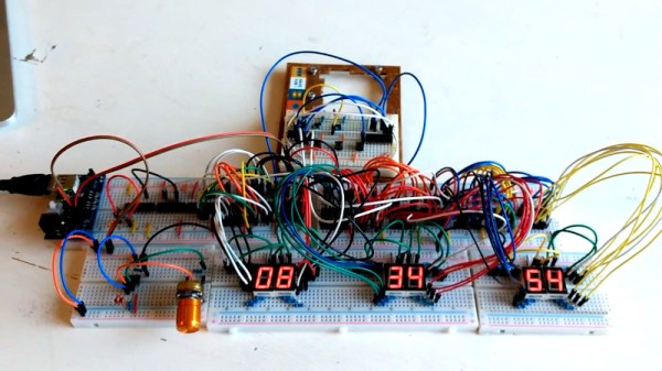
[Erik van Zijst] has had a long career as a programmer, but lacked an understanding of what was happening at a bare metal level. After building a few logic gates out of transistors to get a feel for electronics, he set out to build a working clock using 74-series logic. Naturally, it was quite the adventure. 

The project starts out as many do on the breadboard. The requisite BCD counters and 7-segment displays were sourced, and everything was connected up with a cavalcade of colorful hookup wires. A 32.768 KHz crystal was pressed into service to generate the clock signal, divided down to get a 1Hz output to drive the seconds counter that would then run the entire clock. [Erik] then had to learn some more practical electronics skills, to deal with debouncing buttons for the time setting circuit.

With the clock now functional, [Erik] decided to take things further, aiming to build something more robust and usable. An automatic brightness control was created using a 555 to run a crude PWM dimmer for the LEDs. Additionally, a PCB was designed to replace the temporary breadboard setup. This led to problems with the oscillator that [Erik] couldn’t quite figure out. Rather than continue on the same path, he changed tack, instead replacing the quartz crystal with a modern MEMS oscillator that solved the problem.

It’s a great look at how to construct a working clock from bare logic, and one that serves to remind us just how complex even a seemingly simple device can be. We’ve seen other from-scratch builds before too, like this 777-transistor clock, or this attractive stacked design. Video after the break.

Continue reading “74-Series Clock Gets A MEMS Heart”

Motorized Inline Skates Run On Makita Power

Inline skates can be fun, but like most wheeled contraptions, they’re even better when motorized. With just such a goal in mind, [The Real Life Guys] decided to whip up a set of powered skates, running on Makita power!

To get power to the ground, the third wheel on each skate is modified to have a sprocket attached. A Makita drill is then fitted to the skate, transferring power to the wheel through a 90-degree gearbox and a chain drive. The drill is controlled by removing the trigger from the shell and hooking it up with an extended cable.

It’s a lairy setup that probably takes serious practice to use effectively, but does allow for fancy tricks like differential steering if you really want to show off. It’s a great example of using a powerdrill as an all-inclusive motion setup, with the battery, motor and drivetrain already integrated in a neat, tidy package. It’s not the first time we’ve seen a powered set of ‘skates, either! Video after the break.

Continue reading “Motorized Inline Skates Run On Makita Power”

A Strange Display Gives Up Its Secrets

Providing a display for a project in 2020 is something of a done deal. Standard interfaces and off-the-shelf libraries for easily available and cheap modules mean that the hardest choice you’ll have to make about a display will probably relate to its colour. Three decades ago though this was not such a straightforward matter though, and having a display that was in any way complex would in varying proportion take a significant proportion of your processing time , and cost a fortune. [AnubisTTP] has an unusual display from that era, a four-digit LED dot matrix module, and the take of its reverse engineering makes for a fascinating read.

The LITEF 104267 was made in 1986, and is a hybrid circuit in a metal can with four clear windows , one positioned over each LED matrix. Inside are seven un-encapsulated chips alongside the LED matrices on a golf plated hybrid substrate. The chips themselves are not of a particularly high-density process, so some high-resolution photography was able to provide a good guess at their purpose. A set of shift registers drive the columns through buffers, while the rows are brought out to a set of parallel lines. Thus each column can be illuminated sequentially with data presented on the rows. It’s something that would have saved a designer of the day a few extra 74-series chips, though we are guessing at some significant cost.

This display may seem antiquated to us today, but it wasn’t the only option for 1980s designers. There’s one display driver from back then that’s very much still with us today.

A SpaceX Falcon 9 Will Blow Up Very Soon, And That’s OK

They say you can’t make an omelette without breaking a few eggs, and there are few fields where this idiom is better exemplified than rocketry. It’s a forgone conclusion that when you develop a new booster, at least a few test articles are going to be destroyed in the process. In fact, some argue that a program that doesn’t push the hardware to the breaking point is a program that’s not testing aggressively enough.

Which is why, assuming everything goes according to plan, SpaceX will be obliterating one of their Falcon 9 boosters a little after 8:00 AM EST on Saturday morning. The event will be broadcast live via the Internet, and thanks to the roughly 70% propellant load it will be carrying at the moment of its destruction, it should prove to be quite a show.

This might seem like an odd way to spend $62 million, but for SpaceX, it’s worth it to know that the Crew Dragon Launch Abort System (LES) will work under actual flight conditions. The LES has already been successfully tested once, but that was on the ground and from a standstill. It allowed engineers to see how the system would behave should an abort occur while the rocket was still on the pad, but as the loss of the Soyuz MS-10 dramatically demonstrated, astronauts may need to make a timely exit from a rocket that’s already well on the way to space.
In an actual emergency, the crewed spacecraft will very likely be speeding away from a violent explosion and rapidly expanding cloud of shrapnel. The complete destruction of the Falcon 9 that will be carrying the Crew Dragon during Saturday’s test will serve to create the same sort of conditions the spacecraft will need to survive if the LES has any hope of bringing the crew home safely. So even if there was some way to prevent the booster from breaking up during the test, it’s more useful from an engineering standpoint to destroy it.

Of course, that only explains why the Falcon 9 will be destroyed during this test. But exactly how this properly functioning booster will find itself being ripped to pieces high over the Atlantic Ocean in a matter of seconds is an equally interesting question.

Continue reading “A SpaceX Falcon 9 Will Blow Up Very Soon, And That’s OK”

Analyzing CNC Tool Chatter With Audacity

When you’re operating a machine that’s powerful enough to tear a solid metal block to shards, it pays to be attentive to details. The angular momentum of the spindle of a modern CNC machine can be trouble if it gets unleashed the wrong way, which is why generations of machinists have developed an ear for the telltale sign of impending doom: chatter.

To help develop that ear, [Zachary Tong] did a spectral analysis of the sounds of his new CNC machine during its “first chip” outing. The benchtop machine is no slouch – an Avid Pro 2436 with a 3 hp S30C tool-changing spindle. But like any benchtop machine, it lacks the sheer mass needed to reduce vibration, and tool chatter can be a problem.

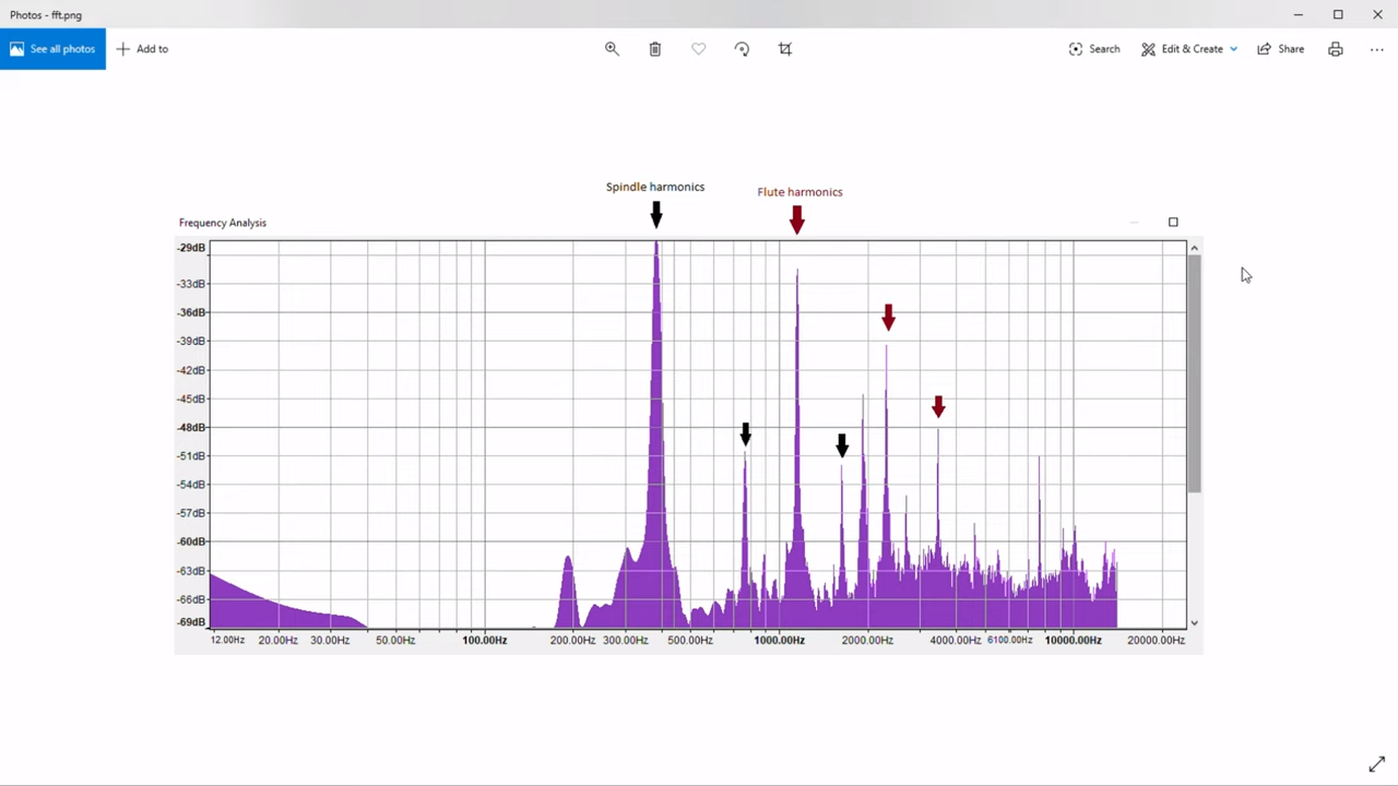
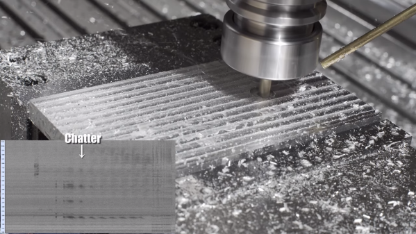
The analysis begins at about the 5:13 mark in the video below, where [Zach] fed the soundtrack of his video into Audacity. Switching from waveform to spectrogram mode, he was able to identify a strong signal at about 5,000 Hz, corresponding to the spindle coming up to speed. The white noise of the mist cooling system was clearly visible too, as were harmonic vibrations up and down the spectrum. Most interesting, though, was the slight dip in frequency during the cut, indicating loading on the spindle. [Zach] then analyzed the data from the cut in the frequency domain and found the expected spindle harmonics, as well the harmonics from the three flutes on the tool. Mixed in among these were spikes indicating chatter – nothing major, but still enough to measure.

Audacity has turned out to be an incredibly useful tool with a broad range of applications. Whether it be finding bats, dumping ROMs, detecting lightning strikes, or cloning remote controls, Audacity is often the hacker’s tool of choice.

Continue reading “Analyzing CNC Tool Chatter With Audacity”