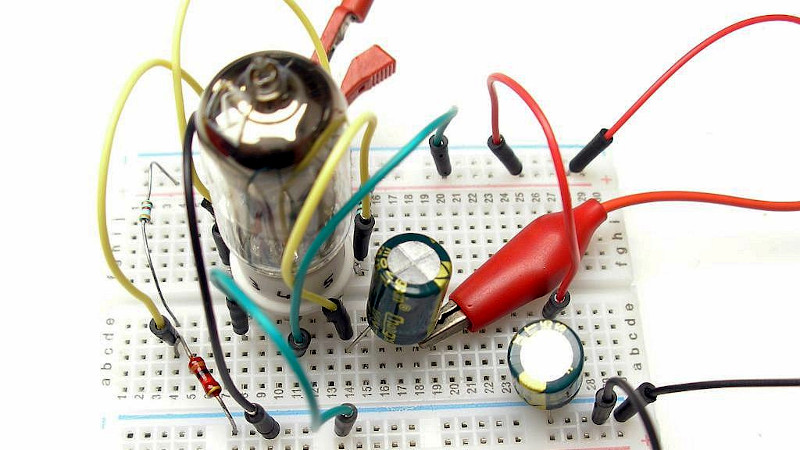
If you’ve ever worked with vacuum tubes, you’ll probably have a healthy appreciation for high voltage power supplies. These components require higher potentials to get those electrons moving, or so we’re told. It’s not the whole truth though, as [Albert van Dalen] demonstrates with his tube preamplifier running from only 3.3 V. If your first thought is that he must have made a flyback converter to step that voltage up to something more useful then you’re in for a surprise, because the single 6J6 pentode really does run from just 3.3 volts. Even its heater, normally supplied with 6.3 V, takes the lower voltage.
The circuit appears at first sight to be a conventional single-ended design, but closer examination reveals a grid bias circuit more reminiscent of a bipolar transistor. This results in a positive grid voltage rather than the more usual negative, and an unusually high 0.3 mA grid current. The cathode current is only 0.15 mA, but the preamplifier delivers a 3.5x gain. There is more detail on his website.
It would be interesting to subject this circuit to a full audio analysis and comparison with a more conventional design. As with so much in the world of audio there’s some smoke and mirrors around what constitutes the so-called “valve sound”, and it’s a question whether the satisfaction comes through the sound itself or the bragging rights of having a unit with a vacuum tube on show. Still, this is a simple enough design which takes few resources to build, so we look forward to seeing further experimentation. Careful though – down the vacuum audio route can lie folly.


Transcription issue – it’s the _plate_ current that is .15 ma. I checked as it seemed impossible for the cathode current to be less than the grid current (pretty basic stuff).
I recall the 6j6 type, the site doesn’t call them that – 5j1 or 6j2, and I found discussion on the net about this – it appears there IS a 6j1 type and an equivalent mil number out there, which surprised me, as I thought I had the entire tube number space memorized (I own a collection of well over 10k tubes).
Ah “the internet” says it’s actually a 6AK5/CK5654/6096 tube. A 6J6 is, after all, a dual triode with a common cathode.
Albert van Dalen is probably using a russian 6Ж2П, equivalent to 6AS6.
Interesting. I’ve made a decent-performing dual-triode regenerative receiver whose plate voltage is as low as 12v, though near full-strength heater current. So high plate voltages aren’t always necessary.
Ken, you should publish that design/project!
Old friend Joe Sousa did some interesting work with various tubes at low voltages (full filament volts) as well, using positive grid bias, and even tried some darlington-like connections that worked. The results weren’t very linear, but workable. He built a reflex 2 tube superhetrodyne that used a rectified stepped up local oscillator signal to provide higher voltage for the audio output(!).
Here’s some of his work with subminiature Russian tubes, a few of which he shared with me (haven’t had time to do cool things with them yet). https://www.radiomuseum.org/forum/russian_subminiature_tubes.html
More on the reflex here:
https://www.radiomuseum.org/forum/one_tube_double_reflexed_superhet_receiver.html
I couldn’t find his design that I mentioned above on the ‘net, it might have been a private communication. I met Joe via a shared love for the old Philbrick opamps and we shared data on them for him to publish for the world:
http://www.philbrickarchive.org/
Thanks Doug! project links below.
… and thanks for the links to the RadioMuseum articles. I do have a small stockpile of Russian subminiature tubes patiently waiting to be employed.
Good job! I once used ECH83, which was rated for 12 V anode voltage if I remember correctly. But 3.3 V and positive grid, well that’s a new one.
Have a link to that? Sounds fun!
Here’s my writeup from 2014. Sadly my images are down. (I might fix later)
http://theradioboard.com/rb/viewtopic.php?f=3&t=5418&p=48817
My circuit is mostly the redesigned version from here:
http://members.iinet.net.au/~cool386/kits/ace.html
The tube I used is a 6H8C, which is a Russian clone of a 6SN7 (dual triode, octal base). Pretty hefty heater current, but it looks so cool…
I still have this receiver. It’s fun to pull it out occasionally and see what’s out there, try some new coils, etc. Household interference can be miserable. I hope to try this out in the country, running off of a car battery.
… and the images are now back on the Radioboard post.
That Ace regen design is really good!
I ,made my own derivate of it with a PCC88 tube and it worked on the first try!
Got usable audio at 12volt plate voltage, but usually ran it at 42V plate as I had a convenient psu for that.
Yes! I was surprised how well it worked. And I followed the original’s idea of just having a a set of terminals along the back for the tuning coil, which makes it simple to try different coil types, as a
It’s great to see all this interest in tube regenerative receivers, Thought I was kind of alone on HaD…
(oh man this site needs comment preview and a short window for making corrections)
Oh groan, this is not a pentode. It is a dual triode with a common cathode.
He might have more gain if second grid is connected to 3.3 directly, as a pentode. Currently 2nd grid is connected to anode, and tube works as triode.
Is there any way you can correct “6J6” to “6J2”? Because they’re completely different tubes and that might confuse newcomers.
There’s a reason why good design uses high voltage for plates. At 3.3V on the Anode, we are far from linear zone of the tube, which will lead to distortion.
Which variant of 6J2? Is it the 6J2P, the 9-pin socket pentode for intermediate frequency amplifier inside old Soviet Union TVs? Is it the simple 6J2 without anything else at the end of its name, meaning the bulb is not glass but metal? Is it the 6J2b, subminiature pentode used in soviet union aircrafts in emergency backup automation systems?
This is the usual “starved plate” design which will never sound tube-ish.
The one and only situation where tubes actually sound as tubes is when they’re overdriven in saturation mode, which almost exclusively happens in guitar amplifiers. Tube amplifiers when saturated produce mostly even harmonics which will make say a guitar chord sound a lot better, but when they’re working linearly there’s no ear in the world which could recognize them from say a mosfet or bipolar or class-D amp. In other words, due to their much higher costs, there’s no point in building HiFi tube amplifiers because they will sound exactly as solid state ones.
Your comment it’s a bit extreme (in the last part) and altough you seem to have basic knowledge you miss 2 fundamental aspects “tube vs SS”
The first one is pure class A behaviour and the second one is how the amplifier clips, tube vs SS…
HiFi tube amps built under cost constraints have very different engineering trade-offs than transistor amps. Gain is expensive, so very little is thrown away to lower distortion or flatten frequency response. Tone controls usually require an additional gain stage. Output transformers to drive speakers are necessary, they limit frequency response and can be very expensive. An a result, a hifi tube amp providing 60 W rms, 20-20kHz +/- 1 dB, less than 1% THD is an expensive rarity. A tube amp flat down to 10 Hz is unheard of, but a transistor amp flat to DC is trivial by comparison.
Most tube amps drive the filaments with AC, resulting in 60 Hz (or 50 Hz) and its harmonics leaking into the sound path. That contributes to the “warm” sound of tube amps.
Crossover distortion is unusual in tube amps, but has to be carefully avoided in non-class-D (or non single-ended) transistor amps.
I no longer have the quality of hearing that can distinguish the sound of mediocre tube design from mediocre transistor design, but some people can.
Debate-able
Been experimenting with tubes and it really depends on how one uses them. Outside of soft-clipping behaviour Tubes are prone to introduce a variety of different distortions. cause microphony, never truly linear behavior, imperfect behaviour due to construction and/or gas mixture, “Heater Hum”, etc. So even when in (supposedly) linear operation Tubes tend to distort and still introduce (sometimes unwanted) effects.
That is at least assuming you are going for a simplistic design without many “HIFi tricks”, hence i call it debate able. If you start to increase complexity/cost and introduce stuff such as Cathode Degeneration, (global) Negative Feedback Loops and replacing Resistors with Constant Current sinks/sources one can heavilly reduce the effect from the tube’s imperfections. Thus achieving closer to true Hi-Fi.
So to say that they always sound the same is kind of a simplification. Tubes are inherently flawed and even outside of guitar amps can still sound Tube-ish, BUT if the goal is true HiFi with little to no Distortion i would indeed question why one would go for tubes. To that the answer is pretty simple though most of the time. Cause Tubes are cool.
The results are as you would expect.
Valves have nonlinearity at the bottom and secondary emission at the top. So it still works but has some nonlinearity.
The configuration is very odd though with the grid connected to anode and suppressor connected directly to plate/ground.
Kind of like using a pentode as a triode.
Though I really haven’t worked with valves since the 70’s
IIRC, severely unheating a tube will make it become “dull” in a short time because of cathode degradation. Why not use low-voltage tubes (“D” series, 1.5V) instead of a 6.3V heater tube ?
wikipedia’s extensive vacuum tube article has no mention of that phenomenon. It does mention that a tube with filament power applied but no cathode current drawn for a long time will tend to emit poorly. If I understand correctly, this is due to the development of a thermal insulating layer between cathode and filament, and a layer on the cathode surface that discourages emission. This is news to me, very interesting.
My understanding is that undervolting the filament should lead to substantial life improvement. In my limited experience, some aspects of tube performance are reduced while the filament is undervolted.
IIRC, underheating the filament will cause only parts of it to really emit electrons, and those parts will get dull faster. Of course, the filament will last longer, but what does that help if nothing comes out of it. Incandescent bulbs also last longer with less than rated current, but they also get dim.
It seems to be dependent on tube type and application. If a circuit’s plate current is well below the maximum allowed for the tube used, then a small reduction in filament voltage does prolong life without reducing performance.
This and other such tube nerding-out here:
https://groupdiy.com/index.php?topic=32746.20
I have heard that this is mitigated if you pre-heat with higher voltage then drop it for running. I believe I remember seeing examples of this in Practical Wireless or similar 60s back issues which I was reading when I was 12 so maybe didn’t catch the subtleties… it was for various “vest pocket” receivers and also maybe a walkie talkie type for the hams, using probably 12V valves with a 6V battery. The idea was something like a buck boost converter which gave a noisy (unsmoothed) boosted DC preheat for a minute or two until it got cut out by a capacitor charging up, then it switched to battery voltage and you could use it.
Interestin, but I have never seen something like that in the wild. There are tubes that must have their heaters rated down; but those are either magnetrons or UHF power parts where electron backbombardment of the cathode is an issue.
Positive grid voltages work wonders:
12SN7 Dual Triode Vacuum Tube Astable Multivibrator
The 6SN7 (the 6V heater variety of the 12V heater tube I used and otherwise identical) was one of the most important components of the first programmable digital computer, the ENIAC, which contained several thousand of them. Every SAGE computer system used hundreds of 5692s, the milspec version of the 6SN7, as flip-flops.
A 9VAC wall wart transformer is used to power this device with 9VAC sent to the 12VAC heater, a full wave rectified 12.7VDC plate voltage, and operation with positive biased grids.
Very cute. Schematics?
Vacuum tubes are VERY linear devices..when used properly. The idea that tubes produce distortion is primarily from people born after their time. Your satellite internet might have been delivered by vacuum tube today….roughly speaking.
Because he could.
Got it.